14 / 46
Siemens RDF300… / RDF340... / RDF400… / RDF600… Basic Documentation CE1P3076.en
Smart Infrastructure 2020-02-21
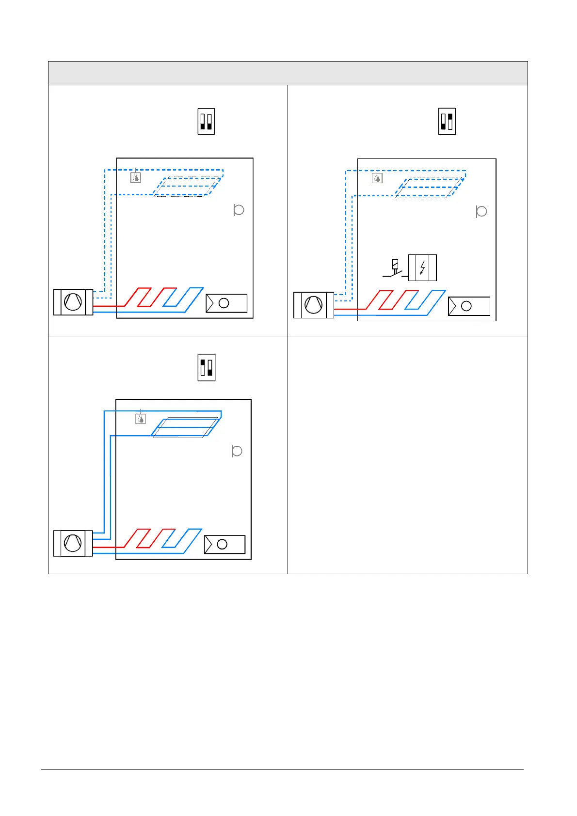
Applications for heat pump systems
Application and output signal, DIP switches, diagram
· 1-stage compressor
ON/OFF
(heating or cooling)
ON
1 2
RDF300...
RDF400...
RDF600...
· 1-stage compressor
ON/OFF
(heating or cooling)
with electrical heater
ON
1 2
RDF300...
RDF400...
RDF600...
N1
T
B1
T
D3
N1T
E1
B1
T
D3
· 1-stage compressor
ON/OFF
(heating and cooling)
ON
1 2
RDF300...
RDF400...
RDF600...
N1
T
B1
T
D3
N1 Thermostat
Terminal Y10/Y11: Heating (H&C) or Heating/Cooling
Terminal Y20/Y21: Cooling (H&C)
B1 Return air temperature sensor or external room
temperature sensor (optional)
E1 Electrical heater D3 Dewpoint sensor
Note: The diagrams above show only the water based fan coil application, but not compressor!
Use with one or two valves for heating and cooling, heating/cooling with
changeover, heating only, or cooling only.
Water-based fan coil
 Loading...