22 / 46
Siemens RDF300… / RDF340... / RDF400… / RDF600… Basic Documentation CE1P3076.en
Smart Infrastructure 2020-02-21
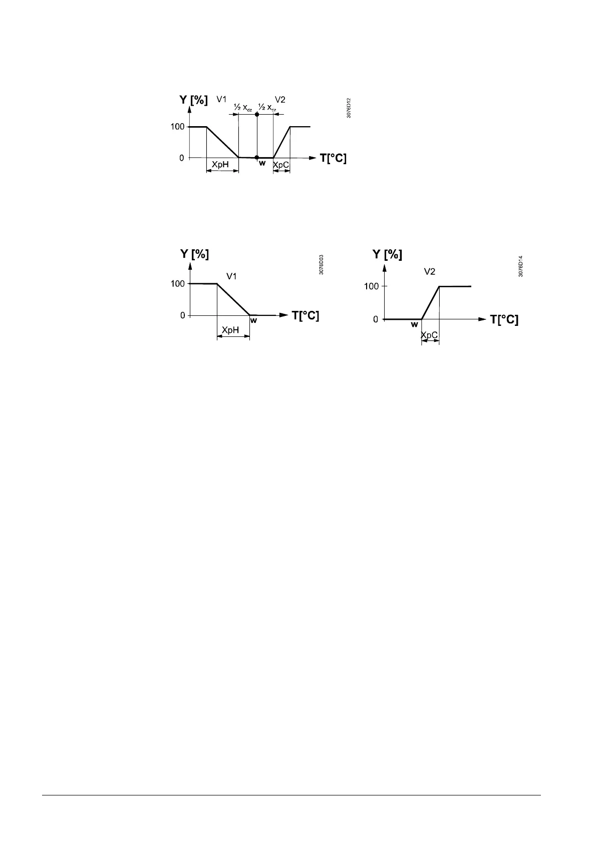
The diagram below shows the control sequence of a continuous PI control.
Heating and cooling mode (P01 = 4 or 3)
T[°C] Room temperature
w Room temperature setpoint
V1 Control command “Valve” Heating
V2 Control command “Valve” Cooling
XpH Proportional band “Heating”
XpC Proportional band “Cooling”
X
dz
Dead zone
Heating mode with manual selection
(P01=2)
Cooling mode with manual selection
(P1=2)
This function (4-pipe modulating) is only available with RDF340 (2 analog outputs
DC 0…10 V are required).
· The diagrams only show the PI thermostat’s proportional part.
· For the fan sequence see section 4.8.
Control sequence
modulating output
Notes:
 Loading...