13 / 14
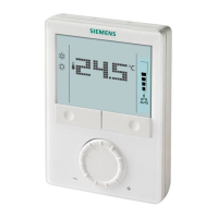
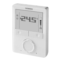
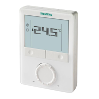
Siemens RDG100KN Room thermostat with KNX communications CE1N3191en
Building Technologies 01 Jun 2010
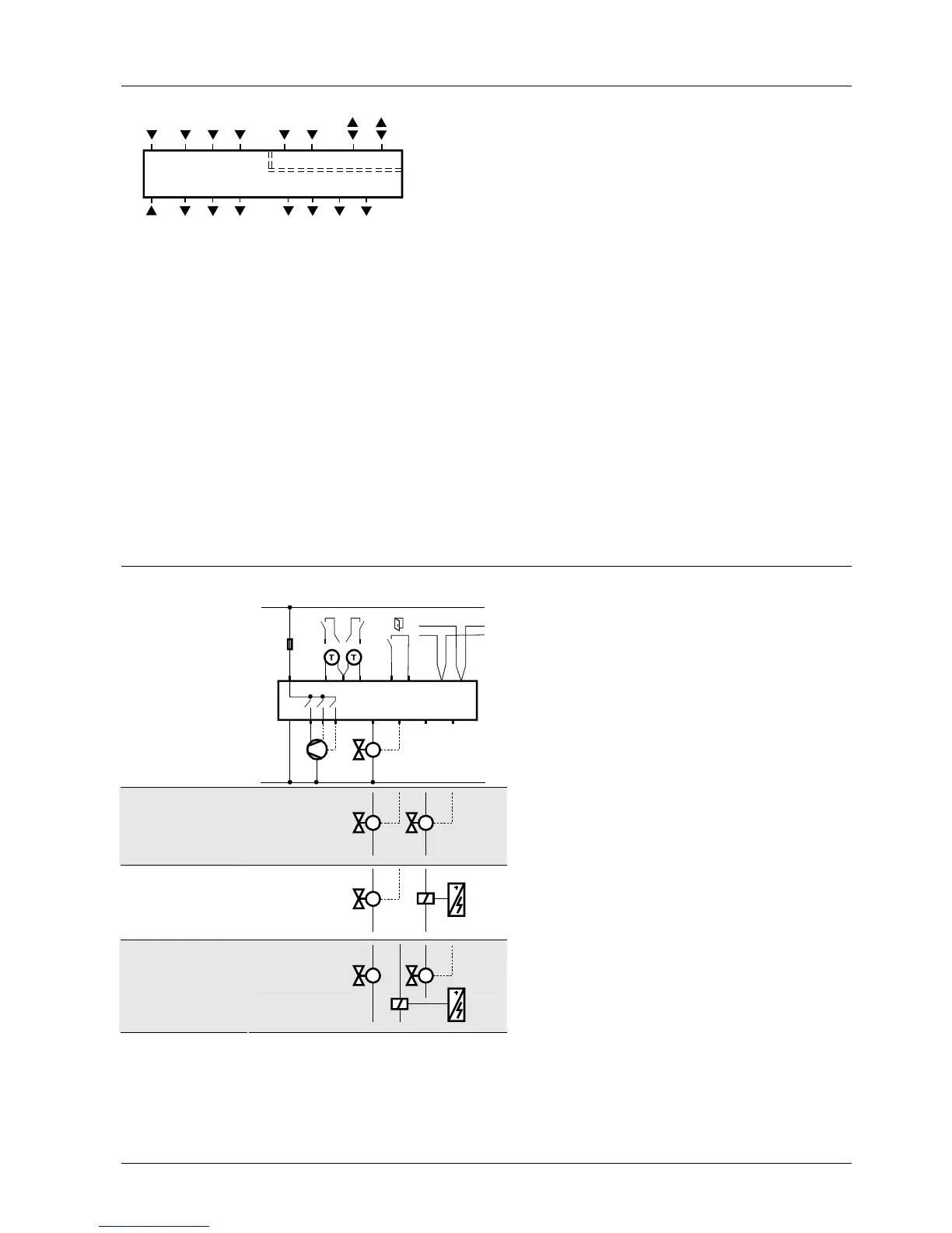
Connection terminals
LX1M
N
Q1 Q2 Q3
Y1
SELV
X2
3191A01
CE+ CE
-
D1 GND
Y2 Y3 Y4
L, N Operating voltage AC 230 V
X1, X2 Multifunctional input for temperature sensor
(e.g. QAH11.1) or potential-free switch
Factory setting:
– X1 = External temperature sensor
– X2 = No function
(function can be selected via parameters P38 / P40).
M Measuring neutral for sensors and switches
D1, GND Multifunctional input for potential-free switch
Factory setting: Operating mode switchover contact
(function can be selected via parameter P42).
Q1 Control output fan speed “low” AC 230 V
Q2 Control output fan speed “medium” AC 230 V
Q3 Control output fan speed “high” AC 230 V
Y1…Y4 Control output “Valve” AC 230 V
(NO contact, for normally closed valves),
output for electric heater via external relay
CE+ KNX data +
CE- KNX data –
Connection diagrams
Application
2-pipe
2-pipe and
radiator
4-pipe
2-stage
2-pipe
and electric
heater
4-pipe
and electric
heater
N1 Room thermostat RDG100KN
M1 1- or 3-speed fan
V1, V2 Valve actuators:
ON/OFF or PWM, 3-position,
heating, cooling, radiator, heating / cooling,
1st or 2nd stage
E1 Electric heater
K Relay
F External fuse
S1, S2 Switch (keycard, window contact, presence
detector, etc.)
S3 Switch at SELV input
(keycard, window contact)
B1, B2 Temperature sensor (return air tempe-
rature, external room temperature,
changeover sensor, etc.)
CE+ KNX data +
CE– KNX data –
L
N
10 A
L
N
AC 230 V
X1 M
X2
N1
M1
Y1
5(2)A
max.
1A
max.
B2
S2
B1
S1
E1
F
3191A12
Q1 Q2 Q3
IIIIII
CE+ CE-
KNX
D1
GND
S3
Y1 Y2
Y1 K
Y1 Y2
K
E1
Y1 Y2 Y3 Y4
 Loading...