12 / 18
Siemens Room temperature controller radio set REV24RF../SET CE1N2206en
Building Technologies 24.04.2008
Commissioning
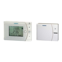
• The room unit and receiver are interconnected at the factory in the RF/SET. As a result,
you do not need to manually connect the two units.
However, you can still manually connect the room unit and the receiver as needed.
See Point "7. Manually connect REV24RF.. and RCR10/868“.
• Remove the black transit tabs; the unit starts to operate as soon as you remove the
transit tabs on the battery contact. : Select desired language by
or .
Confirm by
.
• If possible, mount the receiver temporarily (e.g. using dual-sided adhesive tape) to try
to identify the best possible location for RF reception. To do this, fully wire the
RCR10/868 and close the front cover.
• See Point "4 Test radio link / identify best RF reception location“.
a) Switch on RCR10/868
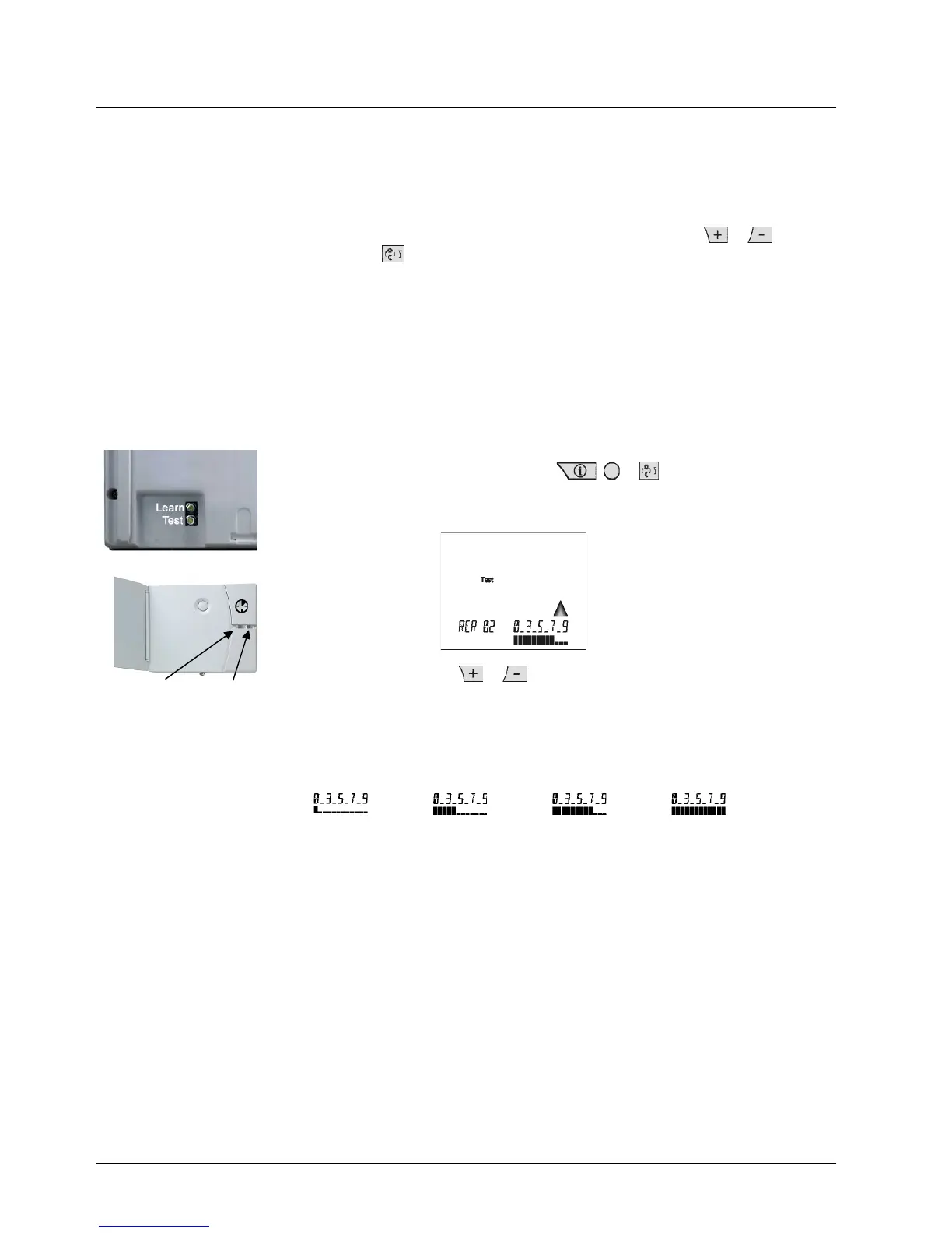
b) Press the Test button on the rear or the REV24RF.. and place the unit in the best RF
reception location. Test the radio link between the room controller and all connected
receivers. On the RCR10/868, LED_2 flashes quickly.
The test turns off automatically after 10
minutes or you can manually end it by
pressing one of the following buttons
: , or .
c) The REV24RF.. shows the quality of the radio link to the connected RCR10/868. If
more than one receiver is connected to the same REV24RF.., the display changes
every 10 seconds from RCR 01 to RCR 02, etc..
Select the receiver with
or . The selected receiver is tested continuously for
1 minute.
d) REV24RF..: The greater the visible bar under numbers 0…9, the better the radio link.
If the bar is below the number 0, radio link is not guaranteed. In this case, move the
room controller to a different location and shorten the distance between
the
REV24RF.. and RCR10/868.
Repeat the test until quality is sufficient.
Insufficient Sufficient Good Very good
e)
RCR10/868: LED_1 also indicates the radio link quality:
Red = Insufficient or no radio link
Orange = Good
Green = Very good
f)
If radio link quality is insufficient, shorten the distance between the REV24RF.. and
RCR10/868.
Repeat the test until quality is sufficient.
a) Switch off power.
b) Mark the place where the RCR10/868 is located.
c) Loosen the wiring as needed.
d) Mount the receiver at the marked location, wire completely and close the housing.
e) Switch on power.
f) The receiver does not require operation after commissioning.
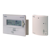
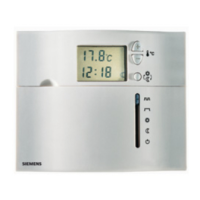
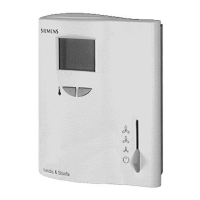
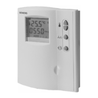
1. REV24RF../SET
2. Switch on the
REV24RF..
3. Temporarily mount
the RCR10/868
4. Test radio link /
Identify best RF
reception location
LED
 Loading...