Installing the Device
2.5 Connecting Power
curs. For more information, refer to the RUGGEDCOM RX1512 User Guide for the
RUGGEDCOM RX1512.
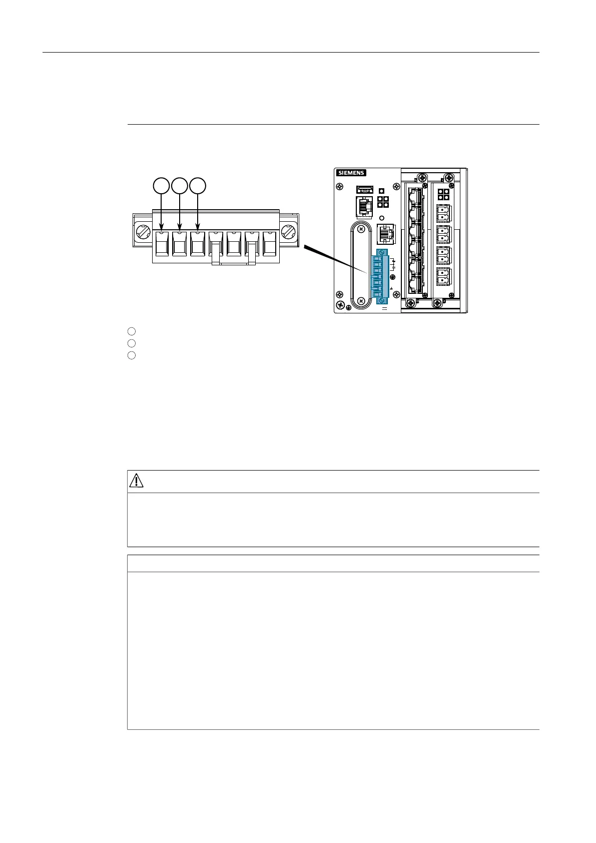
The following shows the proper relay connections.
1
Normally Closed
2
Common
3
Normally Open
Figure2.3 Failsafe Alarm Relay Wiring
2.5 Connecting Power
The RUGGEDCOM RX1512 supports a single low DC power source.
DANGER
Electrocution hazard – risk of serious personal injury or death
Make sure all power sources are off before servicing the power module terminals.
Make sure the power source is off before servicing the power terminal.
NOTICE
• Use minimum #16 gage copper wiring when connecting terminal blocks.
• The maximum wire length between the terminal block and power source must
not exceed 6 m (20 ft) for 24 V power supplies or 18 m (60 ft) for 48 V power
supplies.
• For 125/230 VAC rated equipment, an appropriately rated AC circuit breaker
must be installed.
• For 125/250 VDC rated equipment, an appropriately rated DC circuit breaker
must be installed.
• Equipment must be installed according to applicable local wiring codes and
standards.
RUGGEDCOM RX1512
Installation Manual, 07/2019, C79000-G8976-1057
9
 Loading...