Installing the Device
2.5.2 Testing Dielectric Strength
2. Connect the positive wire from the power source to the positive (+) terminal on
the terminal block.
3. Connect the negative wire from the power source to the negative (-) terminal on
the terminal block.
4. Install a jumper between the surge ground terminal and chassis ground termi-
nal. The surge ground terminal is used as the ground conductor for all surge and
transient suppression circuitry internal to the unit.
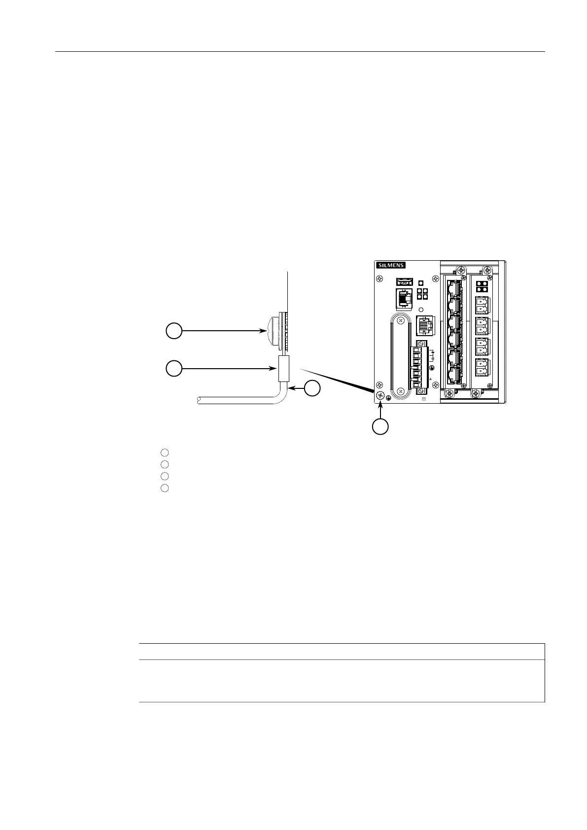
5. Using a #10 ring lug and #10-32 screw, secure a ground wire (or bond point) to
the chassis ground connection on the device. Make sure the lug is tightened to
1.1 N·m (9.5 lbf·in).
1
#10 Ring Lug
2
#10-32 Screw
3
Connection from External Power Source
4
Chassis Ground Connection
Figure2.6 Chassis Ground Connection
6. Install the safety cover over the terminal block. This is mandatory for 48 VDC
and -48 VDC power supplies.
2.5.2 Testing Dielectric Strength
Before performing any dielectric strength or HIPOT (High Potential) testing on the
RUGGEDCOM RX1512 in the field, do the following:
NOTICE
In normal operation, the jumper between the chassis ground and surge ground ter-
minals must be installed for proper operation. Removing the jumper may void the
warranty.
12
RUGGEDCOM RX1512
Installation Manual, 07/2019, C79000-G8976-1057
 Loading...