41
Discrete Inputs/Outputs
Motor Starter Example While the lamp application previously discussed is useful to
explain basic PLC operation, a more practical, and only slightly
more complex, application is start-stop control of an AC motor.
Before examining the PLC application, first consider a hard-
wired approach.
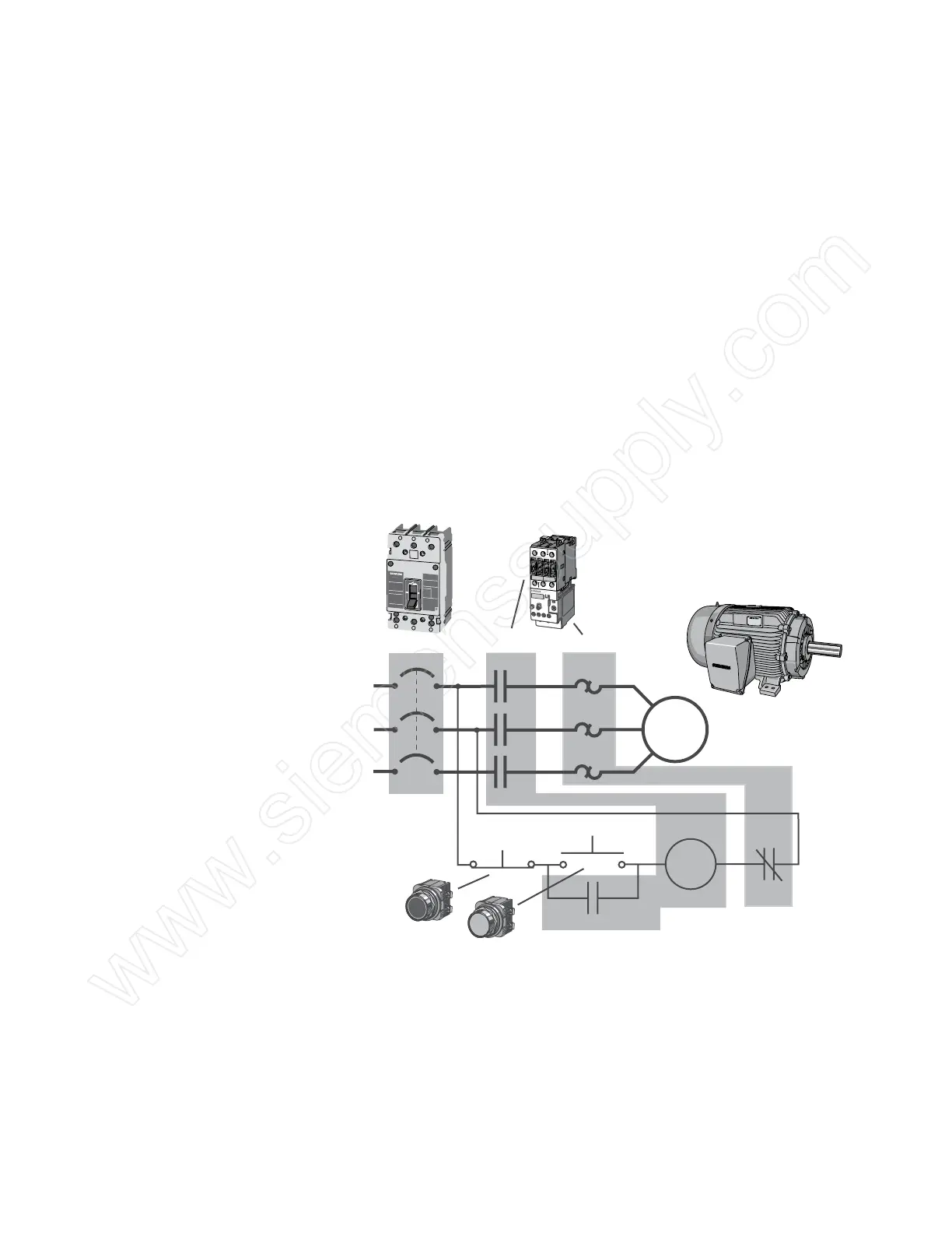
The following line diagram illustrates how a normally open and
a normally closed pushbutton might be connected to control
a three-phase AC motor. In this example, a motor starter coil
(M) is wired in series with a normally open, momentary Start
pushbutton, a normally closed, momentary Stop pushbutton,
and normally closed overload relay (OL) contacts.
O
N
O
F
F
l
O
100
100
Amp
T
ype/T
ip
o
NEG
Frame-EG
Motor
M
Starter Coil
Ma
Start Pushbutton
Stop Pushbutton
Auxiliary Contact
(Holding Circuit)
OL
L1
L2
L3
Circuit Breaker
M
M
M
OL
OL
OL
Contactor Overload Relay
T1
T2
T3
Momentarily pressing the Start pushbutton completes the path
for current flow and energizes the motor starter (M). This closes
the associated M and Ma (auxiliary contact located in the motor
starter) contacts. When the Start button is released, current
continues to flow through the Stop button and the Ma contact,
and the M coil remains energized.

 Loading...


