11.98 Maintenance
Siemens AG 6SE7087-6AC85-0AA0 ENGLISH
8-3
Common Rectifier Operating instructions
Replacing modules in the electronics box
(option)
♦ Undo the securing screws of the modules
above and below the insertion /removal aids
♦ By means of the insertion /removal aids,
carefully pull the module out of the
electronics box, making sure that the
module does not get stuck
♦ Carefully insert the new module in the guide
rails until it moves no further in the
electronics box
♦ Firmly screw down the module with the
securing screws above and below the
insertion / removal aids.
8.2.3 Replacing bridge rectifiers V1
The bridge rectifier is secured with self-tapping screws. When replacing the bridge rectifier, it is imperative to
use original-length screws with locking elements to secure it.
Also use original-length screws when screwing the bridge rectifier to the connecting cables.
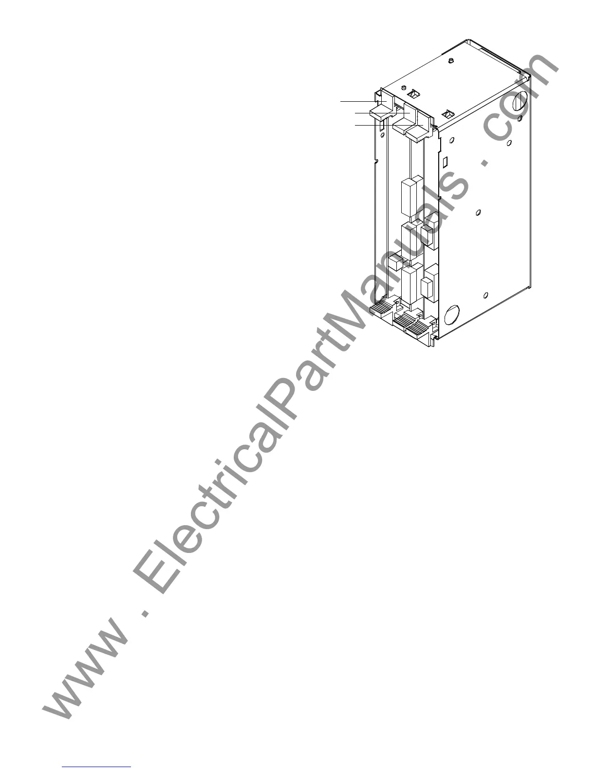
Slot 3 (options)
Slot 1 (PSR)
Slot 2 (options)
Figure 8.2 Electronics box, equipped with PSR (slot 1)
and options (slots 2 and 3)
 Loading...