Connection 11.98
3-4 ENGLISH Siemens AG 6SE7087-6AC85-0AA0
Common Rectifier Operating instructions
3.2 Power supply / control
3.2.1 Electronic power supply / fault signal
The electronic power supply is not included in the scope of supply of the common rectifier.
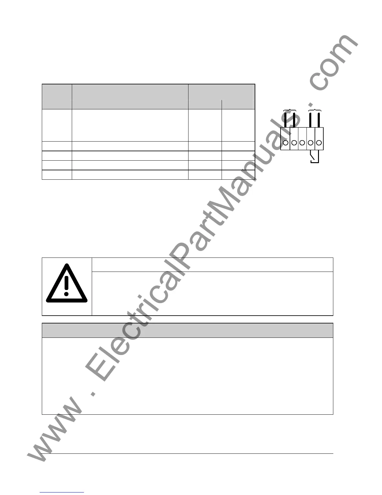
Plug-in terminal X9
Terminal Function description perm. conductor
cross-section
X9 (mm
2
) (AWG)
1 DC 24V (tolerance range 20V - 30V)
2)
max. current consumption 2A at +24V
max. current consumption without options:
size B = 0.5A, size C = 1A
0,2 to 2,5 24 to 14
2 Reference potential 0,2 to 2,5 24 to 14
3 not connected (N.C.) 0,2 to 2,5 24 to 14
4 Fault signal
2)
0,2 to 2,5 24 to 14
5 Fault signal
2)
0,2 to 2,5 24 to 14
Table 3.3 Permissible connection cross-sections for the power supply and the fault signal
Terminal X9.1 fused with fuse T2A/250V träge/time-lag 5x20mm
(19198-T2A/250V Messrs. Wickmann-Werke GmbH respectively
0034.3993 FSD Messrs. Schurter)
Terminal X9.2 fused with fuse T3,2A/250V träge/time-lag 5x20mm
(19198-T3,2A/250V Messrs. Wickmann-Werke GmbH respectively
0034.3998 FSD Messrs. Schurter)
WARNING
For safety reasons, we recommend that a master contactor or other device with a similar
function is fitted on the mains system side which disconnects the unit from the mains
system when the "Fault" contact opens.
In cases where a main contactor is fitted, a latching circuit should be provided for this in
order to prevent unexpected reclosing after faults.
NOTES
The main contactor’s exciter coil must be wired with surge arresters, e.g. an RC network for AC or a diode for
DC.
The 'Fault' relay contact (terminal X9) must be looped directly or indirectly into the main contactor control. Use
of a main contactor is necessary to protect the unit. Connection of a latching relay prevents unexpected
activation when the fault is remedied.
In the event of phase failure, operation of the main contactor without latching leads to cyclic deactivation and
activation of the main contactor because the phase failure signal is suppressed in the event of a mains failure.
Mains failure on the unit arises by virtue of the fact that the main contactor drops out in the event of a
malfunction.
2) Contacts for switching the main contactor between terminals 4 and 5 ; switching voltage AC 230V max. AC 3A at cosϕ ≥ 0.4; max.
switching capacity 1500 VA ; at switching voltage DC 30V max. DC 5A
12345
X9
P
M
ext. SV
DC 24V
AC 230V
1500VA
Fault signal
Figure 3.2 DC 24 V power supply
and fault signal
connection
 Loading...