Communication Interfaces
User Interface, Front Side
You can find a USB connection of type B for the connection to a laptop computer or to a PC on the front side of
the device. A protection cover protects this USB connection against pollution and humidity.
USB User interface
Connection USB type B
Insulation class PELV (Protective Extra Low Voltage) (according to IEC 60255-27)
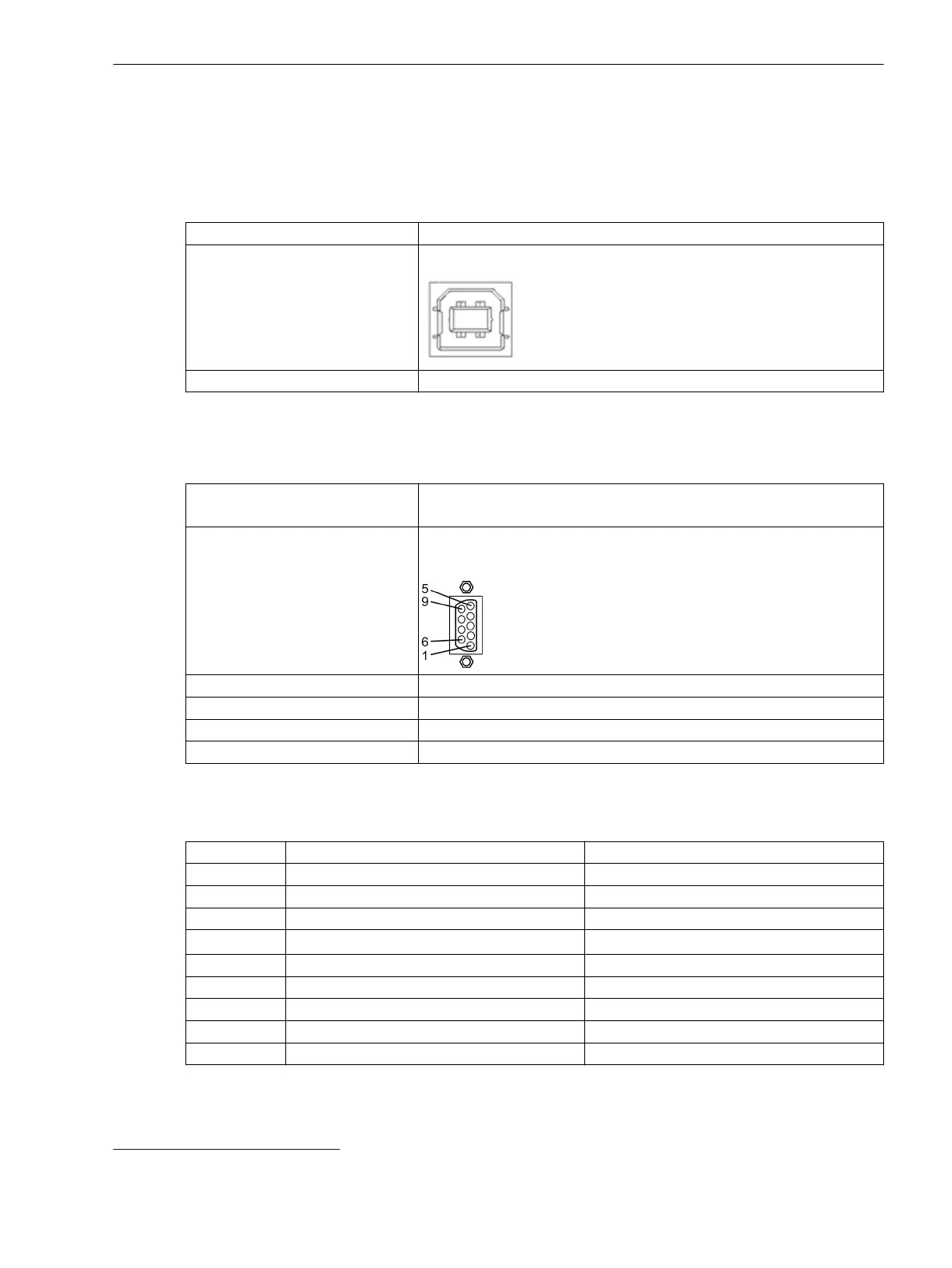
Time-Synchronization Interface (Port G)
The terminal for time synchronization is located on the D-sub 9 interface (position G). Time synchronization
signals for DC 5 V, DC 12 V, and DC 24 V can be processed as an option.
Time Synchronization External synchronization sources, for example, DCF77
IRIG B signal
Connection Rear
D-sub 9
Rated signal voltages DC 5 V, DC 12 V, or DC 24 V (optional)
Test voltage AC 500 V at 50 Hz
Insulation class SELV (according to IEC 60255-27)
Max. line length 10 m (0.39 in)
Table 6-4 Time-Synchronization Connection
Pin Signal Signal Description
1 P24-TSIG DC 24 V input
2 P5-TSIG DC 5 V input
3 M-TSIG Return line Pxx-TSIG
4
M-TSYNC
22
Return line for P-TSYNC
5 Screen Shield potential
6 – –
7 P12-TSIG DC 12 V input
8 P-TSYNC DC 24 V input
9 Screen Shield potential
6.6
22
Only for the PPS signal (GPS)
Technical Data
6.6 Communication Interfaces
SIPROTEC 5, Hardware Description, Manual 217
C53000-G5040-C002-F, Edition 06.2019

 Loading...


