IDLER PULLEY ADJUSTMENT -
44” (112 CM) MODELS ONLY
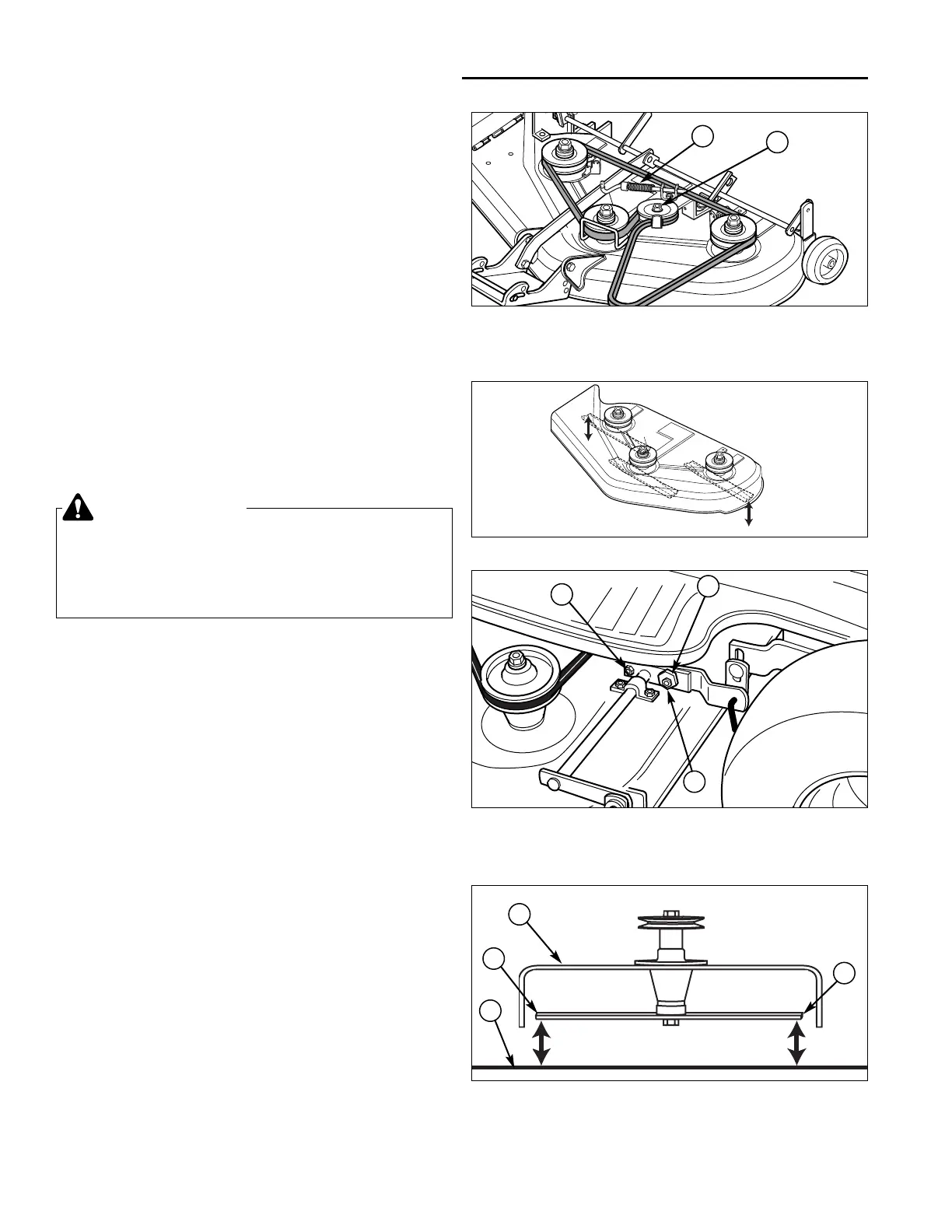
1. Disengage the PTO lever. Set the mower height
adjustment lever to mid-cut position.
2. Loosen the idler pulley capscrew (A, Figure 32b) and
slide the pulley back in the slot to take up more belt
length.
3. Tighten the idler pulley capscrew.
4. Engage the PTO lever. Measure the length of the
compressed clutch spring (B). The spring should be
2-7/8” to 3” (7.3 cm to 7.62 cm) when compressed.
Repeat steps 2-4 if necessary.
NOTE: If adjusting the idler pulley does not take up
enough belt slack, perform the Clutch Rod Adjustment
found on the previous page.
5. Check the mower blade stopping time. The blades
should stop within 5 seconds. If the blades do not
stop within 5 seconds contact your authorized dealer.
Leveling The Mower
If the cut is uneven, the mower may need leveling.
Unequal or improper tire pressure may also cause an
uneven cut. Tire pressure should be as follows:
• Front: 12 - 15 psi (.83-1.0 b)
• Rear: 10 - 12 psi (.56-.83 b)
SIDE-TO-SIDE ADJUSTMENT
1. With the mower installed, place the tractor on a
smooth, level surface such as a concrete floor. Turn
the front wheels straight forward.
2. Check for bent blades and replace if necessary.
3. Place the mower in high-cut position. Arrange the
mower blades so that they are pointing from side-to-
side (Figure 33).
4. See Figure 33. Measure the distance between the
outside tips of the outer blades and the ground. If
there is more than 1/8" (3mm) difference between the
measurements on each side, proceed to step 5. If the
difference is 1/8" (3mm) or less, proceed to Front-to-
Back Leveling.
5. See Figure 34. Loosen the outside nut (A) and tap-
tite screw (C), then turn the eccentric nut (B) to raise
or lower the left side of the deck. When the mower
deck is level, hold the eccentric nut while tightening
the outside nut. Tighten the taptite screw (C).
30
Troubleshooting, Adjustment, & Service
WARNING
Before checking mower, shut off engine and
disengage PTO. Allow all moving parts to stop.
Remove ignition key, then disconnect the spark
plug wire and fasten it away from the spark plug.
Figure 33. Orient Blades Side-to-Side
Figure 34. Side-to-Side Adjustment
A. Outside Nut
B. Eccentric Nut
C. Taptite Screw
A
B
C
Figure 35. Measure Blade Tips to Ground
A. Mower Deck C. Level Ground
B. Blade Tips
A
B
B
C
Figure 32b. PTO Clutch Adj. - 44” (112 cm) Models
A. Idler Pulley Capscrew
B. Clutch Spring
A
B

 Loading...