-17-
No.EX##-OMN0036
Digital input unit
Model Indication and How to Order
EX600-DX
Digital input
Connector, number of inputs and open circuit detection
Input type
Symbol Connector Number of inputs
Open circuit
detection
Symbol Content
B 4xM12 connector (5 pin)
∗
8 inputs No
P PNP
C 8xM8 connector (3 pin) 8 inputs No
N NPN
C1 8xM8 connector (3 pin) 8 inputs Yes
D 8xM12 connector (5 pin)
∗
16 inputs No
E D-sub connector (25 pin) 16 inputs No
F Spring type terminals (32 pin) 16 inputs No
∗: An M12 connector (4 pin) can also be connected.
Names and Functions of Product
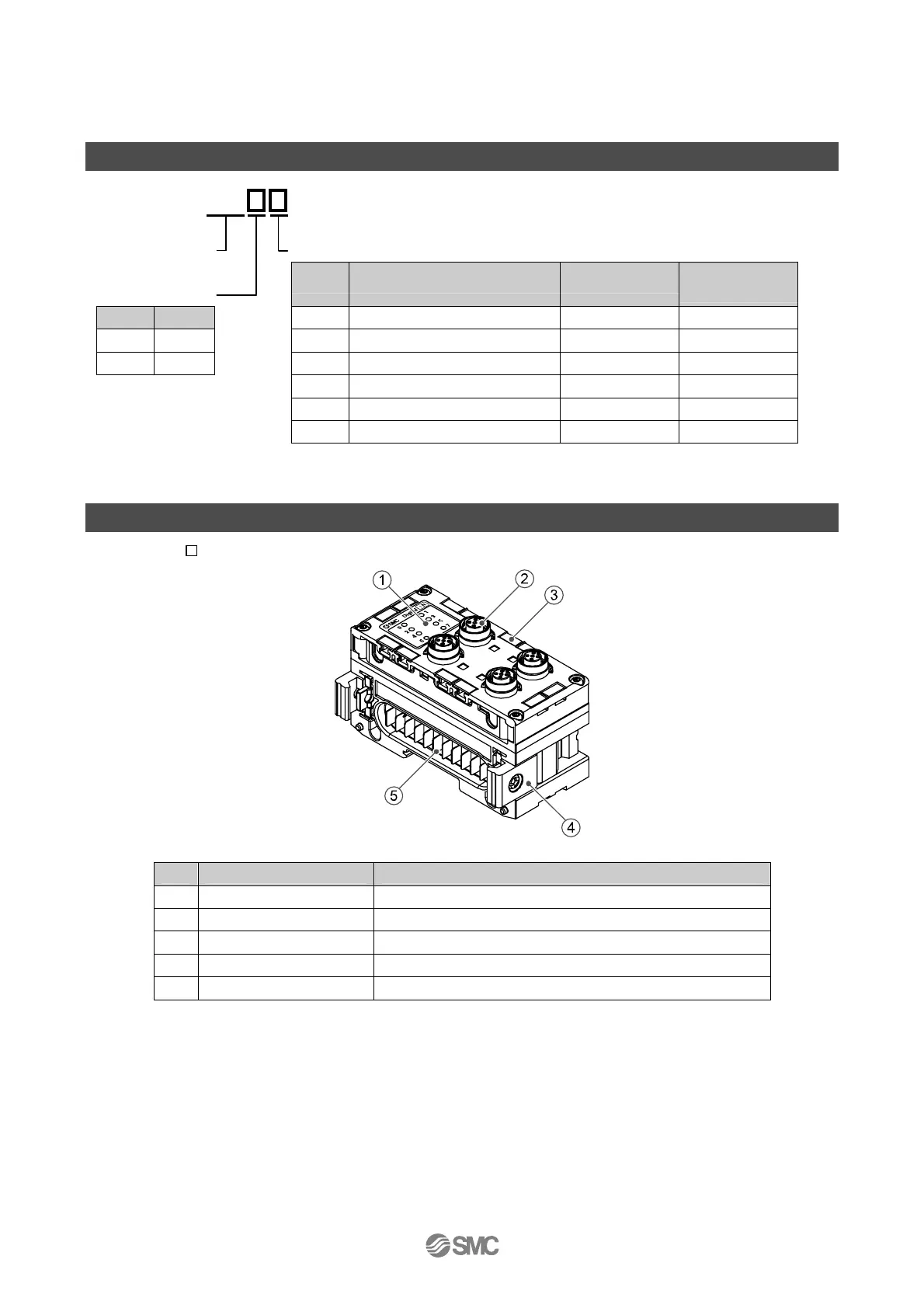
•EX600-DX B
No. Description Function
1 Status display LED Displays the status of the unit.
2 Connector (Input) Connector for input device.
3 Marker groove Groove to mount a marker.
4 Joint bracket Bracket for joining to adjacent units.
5 Unit connector (Plug) Transmits signals and power supplies to adjacent units.

 Loading...
