– 19 –
2 HARDWARE DESCRIPTION
This chapter describes the front panel, rear panel, and LED indicators of the
switch.
FRONT PANEL
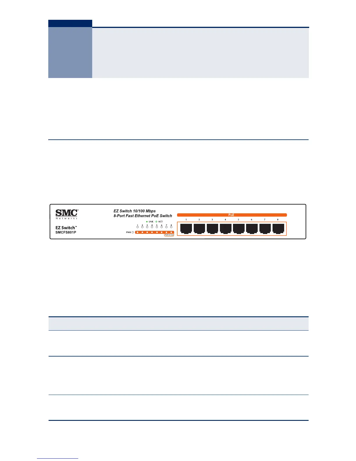
The front panel of SMCFS801P consists of switch LED indicators, and 8 10/100
Mbps RJ-45 ports.
Figure 1: SMCFS801P Switch Front Panel
PORT AND SYSTEM STATUS LEDS
This switch includes a display panel for key system and port indications that
simplify installation and network troubleshooting. The LEDs, which are located
on the front panel, are described in the following table.
Table 1: System and Port Status LEDs
LED Condition Status
PWR On Green The internal power supply is operating normally.
Off The unit has no power connected.
LiK/ACT On Port has established a valid network connection.
Flashing Green Flashing indicates activity.
Off There is no valid link on the port.
PoE In Use On Green A PoE device is connected.
Off No PoE device connected.
 Loading...