- 39 -
7. When the actuator is operated manually (when SVRE output signal is off), supply 24DCV to
the [BK RLS] terminal of the power supply connector.
If the product is operated without releasing the lock, wearing of the lock sliding surface will be
accelerated, causing reduction in the holding force and the life of the locking mechanism.
8. Do not supply 24VDC power supply constantly to the [BK RLS(Lock release)] terminal.
Stop supplying 24VDC power supply to the [BK RLS(Lock release) terminal during normal
operation. If power is supplied to the [BK RLS] terminal continuously, the lock will be released,
and workpieces may be dropped at stop (EMG).
/Refer to the operation manual of LEC (controller) for details of wiring.
6. Electric actuators / Slider type Common precautions
6.1 Design and selection
Warning
1. Do not apply a load in excess of the actuator specification.
A product should be selected based on the maximum work load and allowable moment.
If the product is used outside of the operating specification, eccentric load applied to the guide will
become excessive and have adverse effects such as creating play in the guide, reduced accuracy
and reduced product life.
2. Do not exceed the speed limit of the actuator specification.
Select a suitable actuator by the relationship of allowable work load and speed.
Noise or reduction of accuracy may occur if the actuator is operated in excess of its specification
and could lead to reduced accuracy and reduced product file.
3. Do not use the product in applications where excessive external force or impact force is
applied to it.
This can lead to premature failure of the product.
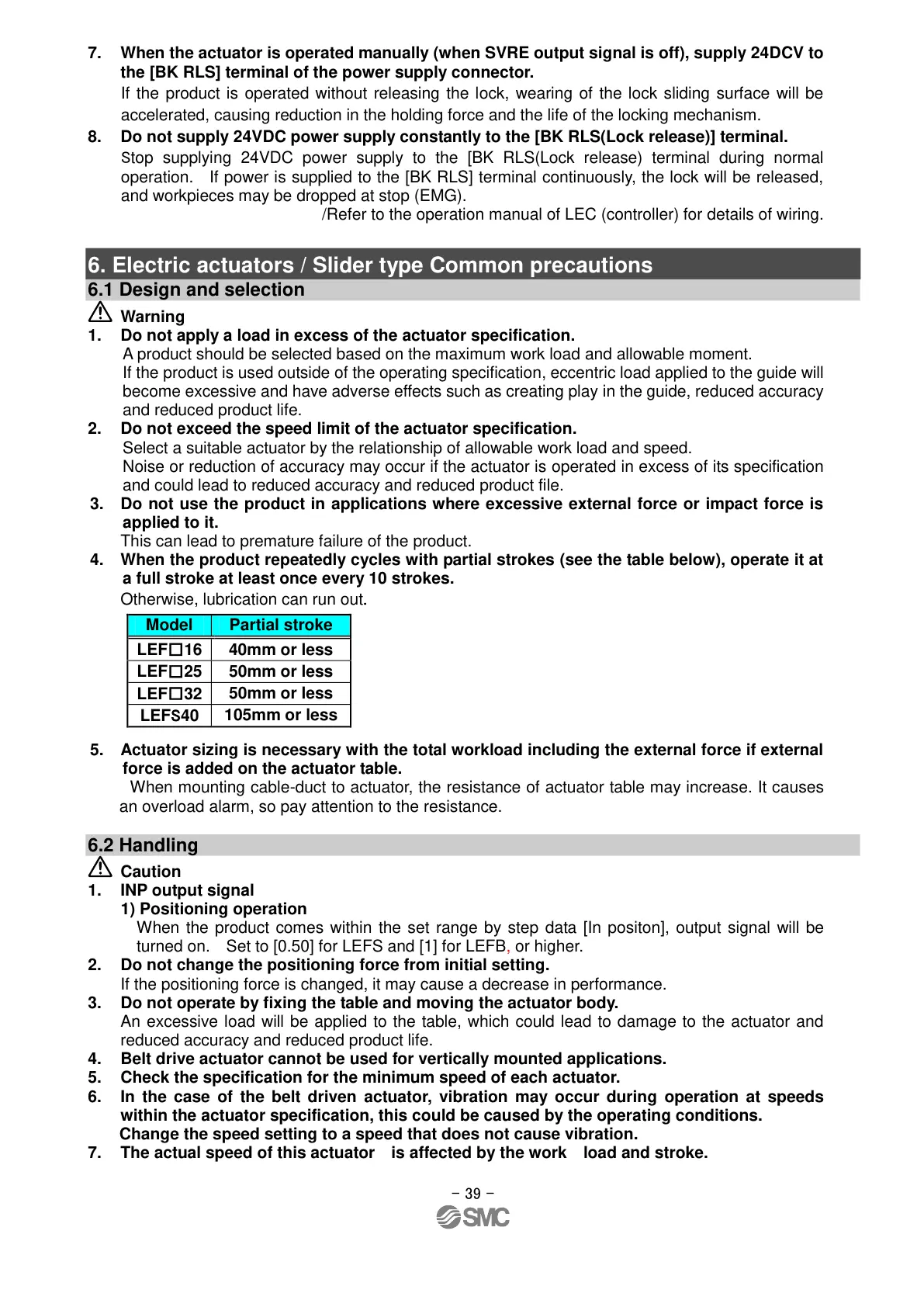
4. When the product repeatedly cycles with partial strokes (see the table below), operate it at
a full stroke at least once every 10 strokes.
Otherwise, lubrication can run out.
5. Actuator sizing is necessary with the total workload including the external force if external
force is added on the actuator table.
When mounting cable-duct to actuator, the resistance of actuator table may increase. It causes
an overload alarm, so pay attention to the resistance.
6.2 Handling
Caution
1. INP output signal
1) Positioning operation
When the product comes within the set range by step data [In positon], output signal will be
turned on. Set to [0.50] for LEFS and [1] for LEFB, or higher.
2. Do not change the positioning force from initial setting.
If the positioning force is changed, it may cause a decrease in performance.
3. Do not operate by fixing the table and moving the actuator body.
An excessive load will be applied to the table, which could lead to damage to the actuator and
reduced accuracy and reduced product life.
4. Belt drive actuator cannot be used for vertically mounted applications.
5. Check the specification for the minimum speed of each actuator.
6. In the case of the belt driven actuator, vibration may occur during operation at speeds
within the actuator specification, this could be caused by the operating conditions.
Change the speed setting to a speed that does not cause vibration.
7. The actual speed of this actuator is affected by the work load and stroke.
2021-05-2010:32
DW913599
 Loading...


