DRM4/8
+3.3V
DRM0
GND GND
1 2
3
4
5
6 7 8
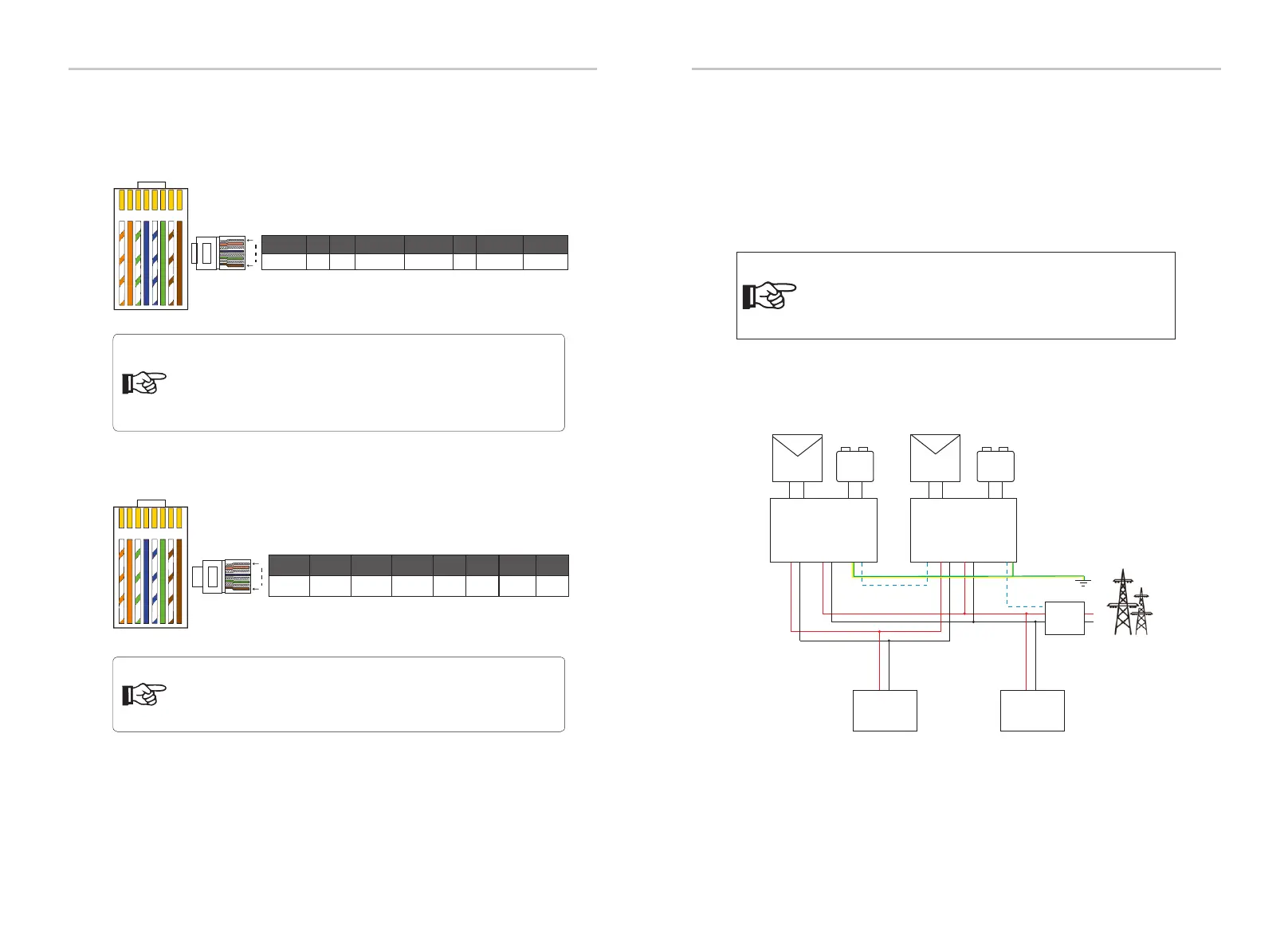
The BMS pin is defined as follows:
The DRM pin is defined as follows:
1 2
3
4
5
6 7 8
DRM1/5 DRM2/6 DRM3/7
1 2 3 4 5 6 7 8
1
8
Ø BMS communication cable
Ø DRM communication cable
1
8
BMS_CANH
GND
BAT_TEMP
GND
BMS_CANL
2
3
4
5
6 7 8
1
X
BMS_485A BMS_485B
Ø System Diagram
6.5.3 Parallel Connection
Electrical Connection
Electrical Connection
56
57
Slave
Master
L N
L N
CAN
Grid
PV+ PV- PV+ PV-
+ -
Battery
+ -
Battery
L
N
PE
Meter
485
L N
L N
Meter
EPS EPS
GridGrid
Inverter Inverter
single-phase
Normal Load
NL
CAN
single-phase
Critical Load
N
L
PE
System diagram applied to electric meters:
Notice!
D series& M series + X1 MATEBOX BASIC supports parallel
function. M series + X1 MATEBOX ADVANCED does not
support parallel function.
Notice!
The BMS port on the inverter is the communication port for
connecting the battery. The communication port on the lithium
battery must be consistent with the definition of pins 4, 5, 7, and
8 above.
The series inverters provide parallel function, and up to 2 inverters can be
connected in a system. In this system, one inverter is set as the "master
inverter", and the other inverter is switched to the "slave inverter" state,
and the inverters are connected to communicate through the CAN line.
The converter "controls the "slave inverter".
Notice!
At present, there are only PIN6 (DRM0) and PIN1 (DRM1 /5), and
other PIN functions are under development.
 Loading...