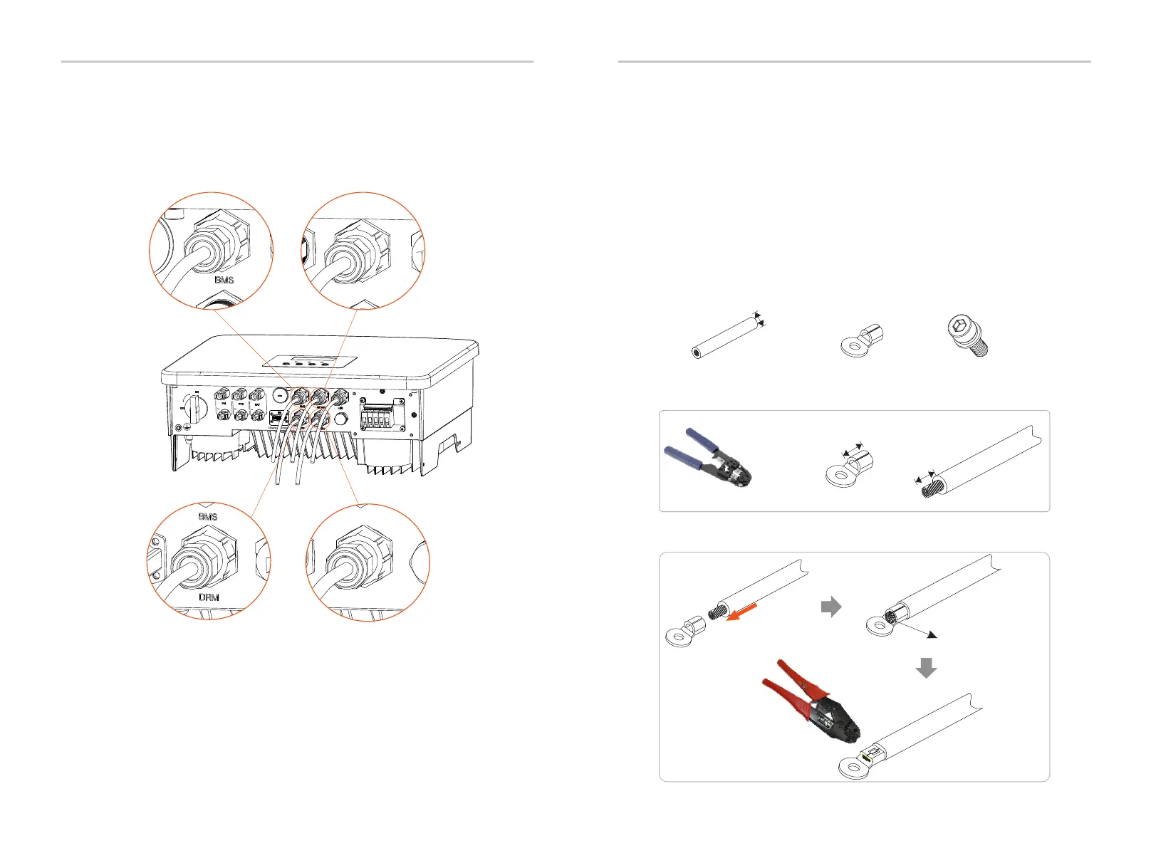
Ø Ground connection steps
C
One-core cable (4 mm)
4 mm
Hexagon socket screws
OT terminal
Diagonal pliers
L2=L1+3 mm
L1
Leaking cable
Crimping Tool
Meter/CT
Meter/CT
COM/LCD
Electrical Connection
Electrical Connection
6.6 Grounding Connection (Mandatory)
68
69
Step 1. Prepare a one-core cable (4 mm), and then find the ground
terminal in the accessories.
The user must make two ground connections: one shell grounding, and
one equipotential grounding.This prevents electric shock.
Step 5: Finally, find the corresponding COM, METER, CT, DRM, LCD poets
on the inverter and insert the communication cable into the corresponding
ports.
Notice: If the PV end of the inverter is not connected with earth , the
inverter will turn on a red light Inspect and report ISO Fault. This inverter
complies with IEC 62109-2 clause 13.9 for earth fault alarm monitoring.
The ground wire port of the series inverter has been
connected, and the D series needs to be wired according to the
following steps.
Step 2. Strip the grounding cable insulation(length”L2"), insert the stripped
cable into the ring terminal, and then clamp it.
Step 3. Insert the stripped cable into OT terminal and tighten the terminal
with a terminal crimping tool.
 Loading...