16
HCD-DX155/DX255
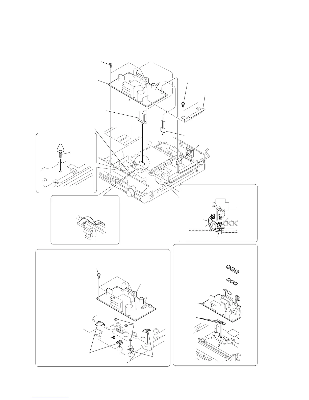
3-8. POWER BOARD
5
shield (H/L)
2
connector (CN3002)
3
connector (CN901)
1
connector (CN515)
4
two screws (+BV 3)
6
five screws (+PWH 3
×
8)
7
POWER board
After twist the harness once,
install the connector .
POWER board
MAIN board
When re-assembling, leave 30 mm between
harnesses A and B for safety.
harnesses A
harnesses B
clamp
30mm
pc board
holder
(bottom side)
two claws
Installing the pc board holder
INSTALLING THE POWER BOARD
(DX155 : SP, AUS, E3)
q;
pc board
holder
1
two covers (FJ)
2
two covers (FJ)
3
three washers
4
install the PC board holder
5
POWER board
6
five screws (+PWH 3
×
8)
4
6
5
1
2
3
When re-assembling, attaching the
heat radiation sheets on the chassis first,
and then attach POWER board.
heat radiation sheets
×
6
(DX155 : SP, AUS, E3)
heat radiation sheets
×
3
(Except DX155 : SP, AUS, E3)
heat radiation
sheets
POWER
board
Ver. 1.2
 Loading...