28
HCD-DX155/DX255
SECTION 5
ELECTRICAL ADJUSTMENT
DVD SECTION
When the base unit is replaced, perform the adjustment and the
measurement as shown below in this order.
1) MIRROR TIME ADJUSTMENT (See page 25)
2) EXECUTING IOP MEASUREMENT (See page 27)
[TEST DISC LIST]
Be sure to use the DVD disc that matches the signal standards of
your region.
• CD
YEDS-18 (Part No.: 3-702-101-01)
PATD-012 (Part No.: 4-225-203-01)
• DVD SL (Single Layer)
NTSC : HLX-503 (Part No.: J-6090-069-A)
HLX-504 (Part No.: J-6090-088-A)
PAL : HLX-506 (Part No.: J-6090-077-A)
• DVD DL (Dual Layer)
NTSC : HLX-501 (Part No.: J-6090-071-A)
HLX-505 (Part No.: J-6090-089-A)
PAL : HLX-507 (Part No.: J-6090-078-A)
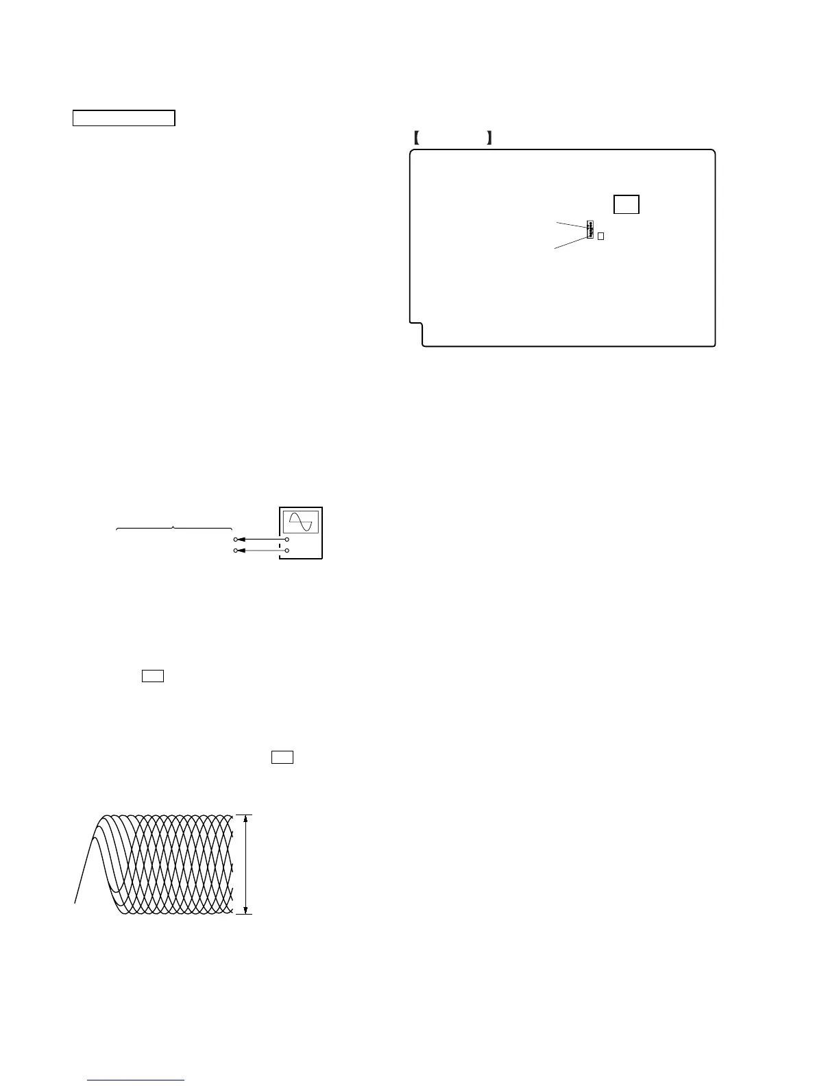
[RF Level Check]
Connection:
Procedure:
1. Connect an oscilloscope to CN1105 pin 6 (RFMON) and
CN1105 pin 3 (GND) on the MAIN board.
2. Turn the power on.
3. Insert the CD test disc (refer to the TEST DISC LIST), and
press the H button to play the disc back.
4. Confirm that oscilloscope waveform is clear and check RF
signal level is correct or not.
Note: A clear RF signal waveform means that the shape “◊” can be
clearly distinguished at the center of the waveform.
5. Eject the CD disc, and insert the DVD SL test disk (refer to
the TEST DISC LIST), and press the H button to play the
disc back.
Checking Location: MAIN board (Side A)
+
–
CN1105 pin
6
(RFMON)
CN1105 pin
3
(GND)
oscilloscope
MAIN board
RF signal waveform
VOLT/DIV: 200 mV
TIME/DIV: 500 ns
level: 0.57 to 1.1 Vp-p (CD)
0.58 to 1.23 Vp-p (DVD
 Loading...