7
Locations and Functions of Parts
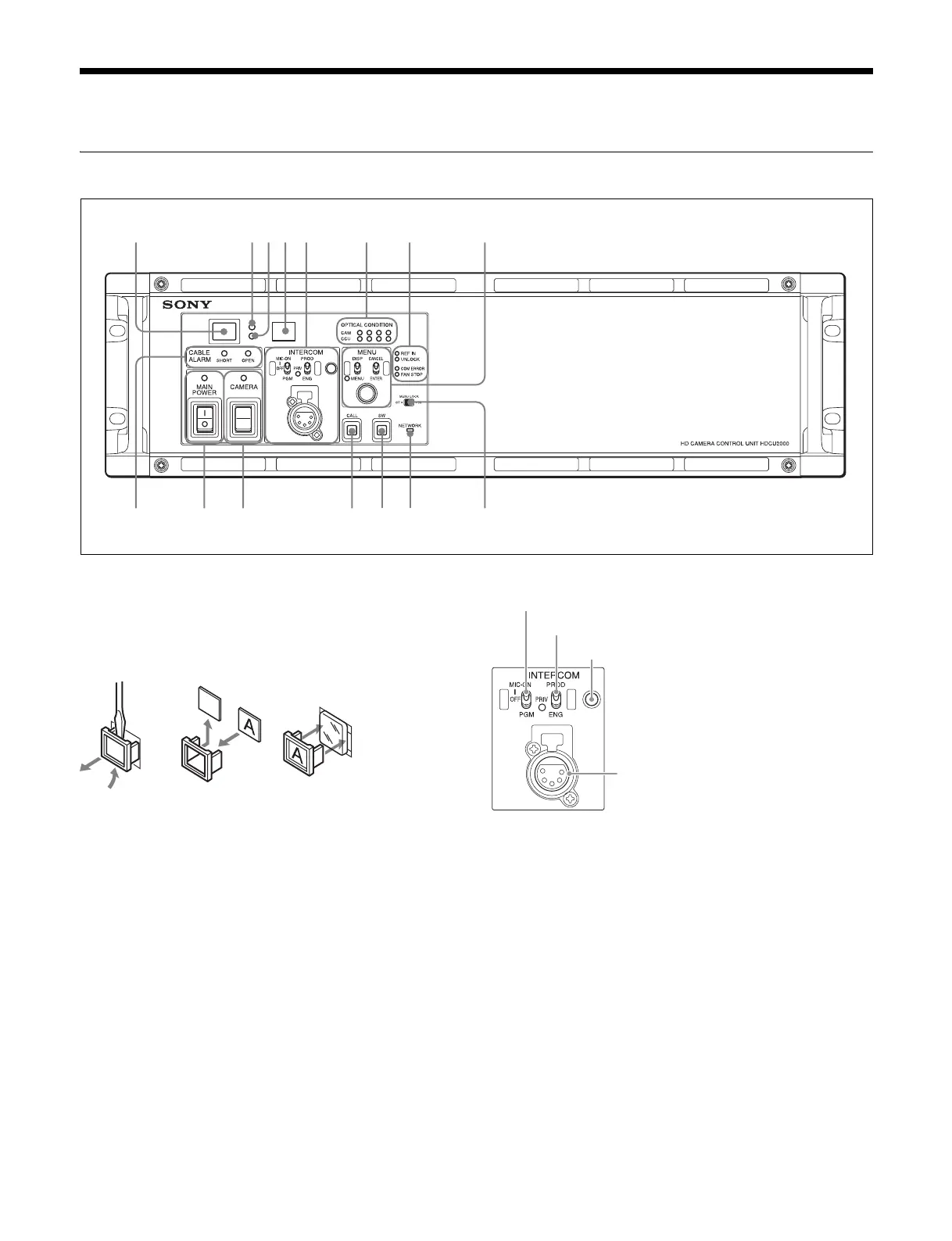
HDCU2000 Front Panel
a Red tally indicator
Lights in red when this unit receives a red tally signal. When
the CALL button on the MSU-1000 series Master Setup Unit,
RCP-1000 series Remote Control Panel, etc., is pressed, this
indicator will go out if previously lit, and light up if previously
off. You can attach the supplied number plate here.
b Yellow tally indicator
Lights in yellow when this unit receives a yellow tally signal.
c Green tally indicator
Lights in green when this unit receives a green tally signal.
d CCU number display
The camera number set via the CCU menu is displayed.
e INTERCOM audio input/output and control block
• MIC/PGM (microphone/program) switch
ON: Turns the headset microphone on.
OFF: Turns the headset microphone off.
PGM: Selects program audio output. In this mode, the
INTERCOM knob adjusts the headset program audio
level.
• INTERCOM (intercom select) switch
Selects the intercom signal input/output connection source for
the INTERCOM connector on the front panel.
PROD: Connects the producer line.
PRIV: Blocks the connection to the producer line or engineer
line, allowing private intercom talk between the CCU and
the camera.
ENG: Connects the engineer line.
• PRIV (Private) indicator
Lights when the intercom is in private mode.
• INTERCOM (intercom adjustment) knob
Adjusts the receiver audio level of the intercom.
• INTERCOM connector (XLR 5-pin)
1 234
qsqa09
8765
qd qf qg
MIC/PGM (microphone/program) switch
INTERCOM (intercom select) switch
INTERCOM (intercom adjustment) knob
INTERCOM connector

 Loading...


