10
When the camera number is not 0, the IP address and subnet
mask of the LAN COM connector are displayed scrolling for a
fixed time only when the DISP/MENU lever is held up in the
DISP position for 3 seconds.
e SIGNAL BAR indicator
Indicates the output status of the video signal.
During gray signal output: Off
During color bar output: Lights in the color specified with the
MAINTENANCE t <FRONT PANEL> t SIGNAL BAR
t READY COLOR menu item.
During camera video output: Lights in a white flowing
pattern.
f CABLE ALARM indicators
OPEN: Lights up when a camera is not connected to the
CAMERA FIBER connector on the rear panel of this unit
via an optical fiber cable. Power is not supplied to the
camera while this indicator is lit.
SHORT: Lights up when an overcurrent flows the through the
optical fiber cable. Power is not supplied to the camera
while this indicator is lit.
g CABLE CONDITION (signal reception status)
indicators
Indicates the communication status of the camera (CAM) and
camera control unit (CCU).
When the two indicators on the right (green) are lit:
Reception status is excellent.
When the second indicator from the right (green) is lit:
Reception status is good.
When the second indicator from the left (yellow) is lit:
Reception status is low.
When the indicator on the left (red) is lit: Reception status
is at the lowest level.
h Status display indicator
REF IN (green): Indicates presence of REFERENCE input
signal.
UNLOCK (red): Not locked to the REFERENCE input signal.
RCP/MSU: Displays the status when there is a remote control
panel connected.
On: Indicates that external control equipment (MSU-1000/
1500 Master Setup Unit, RCP-3000/1000 series Remote
Control Panel, or other equipment) is connected.
Off: Indicates that external control equipment is not
connected.
For details, see “NETWORK Menu” (page 75).
NETWORK: Displays the network genlock status when using
the HKCU-SFP50 ST 2110 Interface Kit.
Low-speed flashing: PTP master not detected
High-speed flashing: Locking to PTP master
Lit: Locked to PTP master
Not lit: Network genlock setting disabled
ALARM: Lights when various errors occur.
FAN STOP: Lights when the fan is stopped.
i Filter cover
Remove the screws on the left/right of the filter cover to
remove the filter cover.
The filter (black sponge) is placed under the cover. If the filter
becomes dirty, you can remove it and clean it with cold or
warm water. When using a detergent, use a neutral solution.
Be sure to dry the filter thoroughly before replacing it on the
unit.
j Guard bar
Do not pull the guard bar with excessive force.
k POWER indicators
CAM: Lights when power is being supplied to the camera.
MAIN: Lights when the unit is turned on. In addition, this
flashes when a fan error occurs.
l POWER switch
Turns the entire camera system on and off, including the unit,
the camera, and the RCP-3000/1000 series Remote Control
Panel connected to the REMOTE connector of this unit.
Switch to “
?” to
turn the power on, and switch to “a” to turn the
power off.
m Menu lock switch
Locks out operation of the front panel menu operation area.
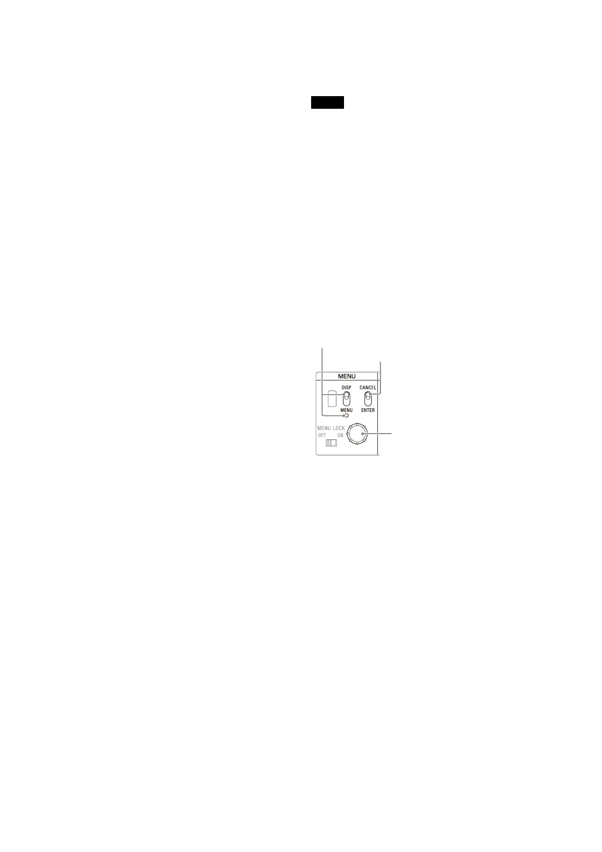
n MENU control block
• DISP/MENU lever and indicator
Selects the status display or setup menu display. In setup
menu mode, the indicator turns on.
When the camera number is not 0, the IP address and subnet
mask of the LAN COM connector are displayed on the CCU
number display scrolling for a fixed time only when the DISP/
MENU lever is held up in the DISP position for 3 seconds.
When <OUTPUT FORMAT1> t SDI-OUT4 t MONITOR is
set to C, you can return to the M setting for MONITOR by
holding the DISP/MENU level down in the MENU position for
3 seconds.
• CANCEL/ENTER lever
In setup menu mode, used to cancel and enter settings.
• CONTROL knob (rotary encoder)
In status screen mode, used to change the displayed page. In
setup menu mode, used to move the cursor on a page and to
change menu settings.
Pushing the knob has the same function as setting the
CANCEL/ENTER lever to ENTER.
Note
DISP/MENU lever and indicator
CANCEL/ENTER lever
CONTROL knob
 Loading...


