1-1 (E)
MKS-8080/8082
Section 1
Service Overview
1-1. Cabinet Removal/Installation
n
Install them in the reverse order of the removal procedure.
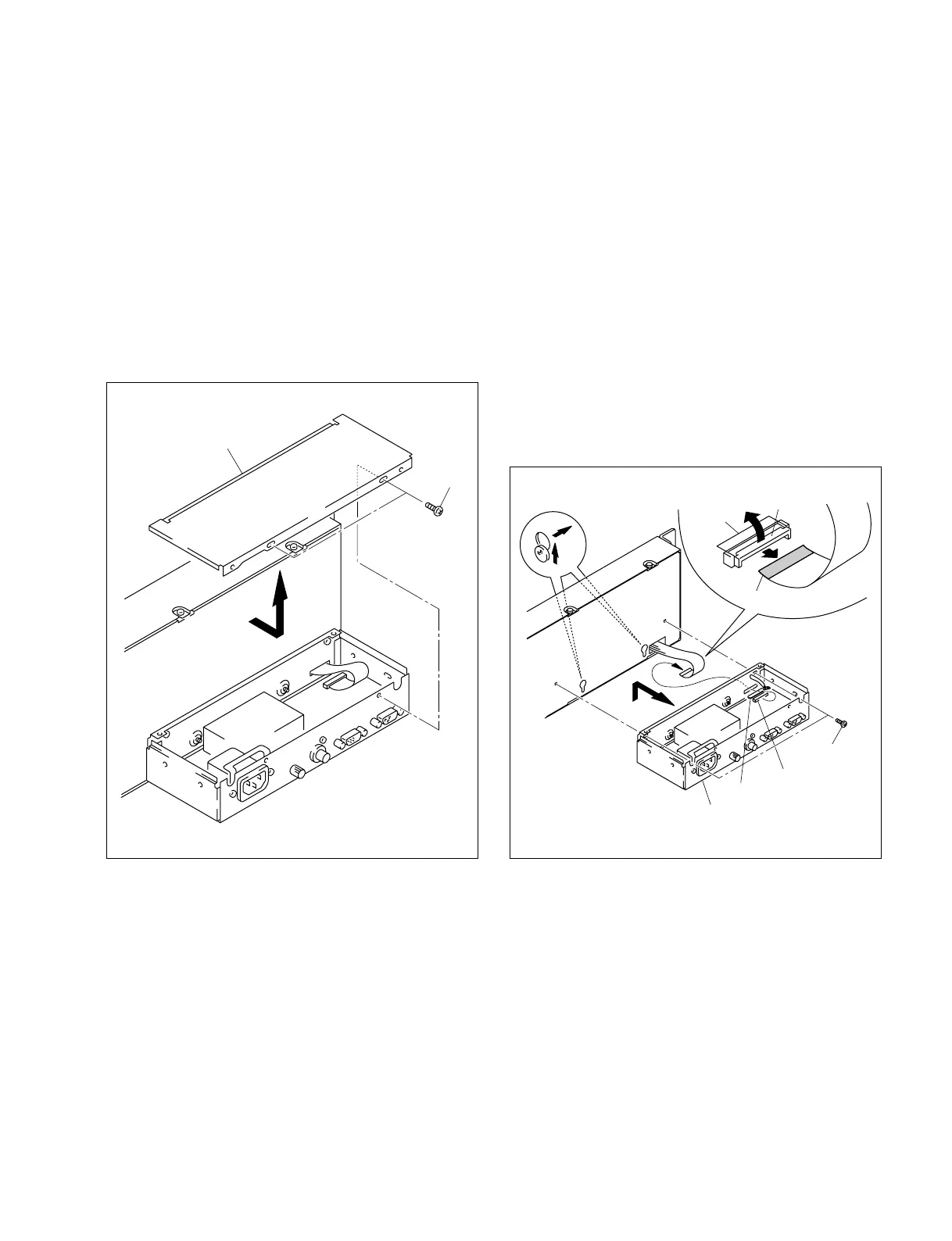
1-1-1. Removal of Top Plate
Remove the two screws, then remove the top plate in the
direction indicated by the arrow.
1-1-2. Removal of CPU Box
1. Remove the top plate. (Refer to Section 1-1-1.)
2. Remove the two screws.
3. Raise the wiring clip holding the flexible card wire.
4. Pull portion A of the connector (CN1) in the direction
indicated by arrow 1 and unlock it. Pull the flexible
card wire in the direction indicated by arrow 2.
5. Remove the CPU box in the direction indicated by
arrow 3.
n
When installing the flexible card wire, put it with the blue
band up.
PSW 3x6
Top plate
CN1
CPU box
PSW 3x6
Wiring clip
3
1
2
Portion A
CN1
Blue band
(The illustration indicates MKS-8082.) (The illustration indicates MKS-8082.)
 Loading...