5-10
1-3. CAMERA SYSTEM ADJUSTMENTS
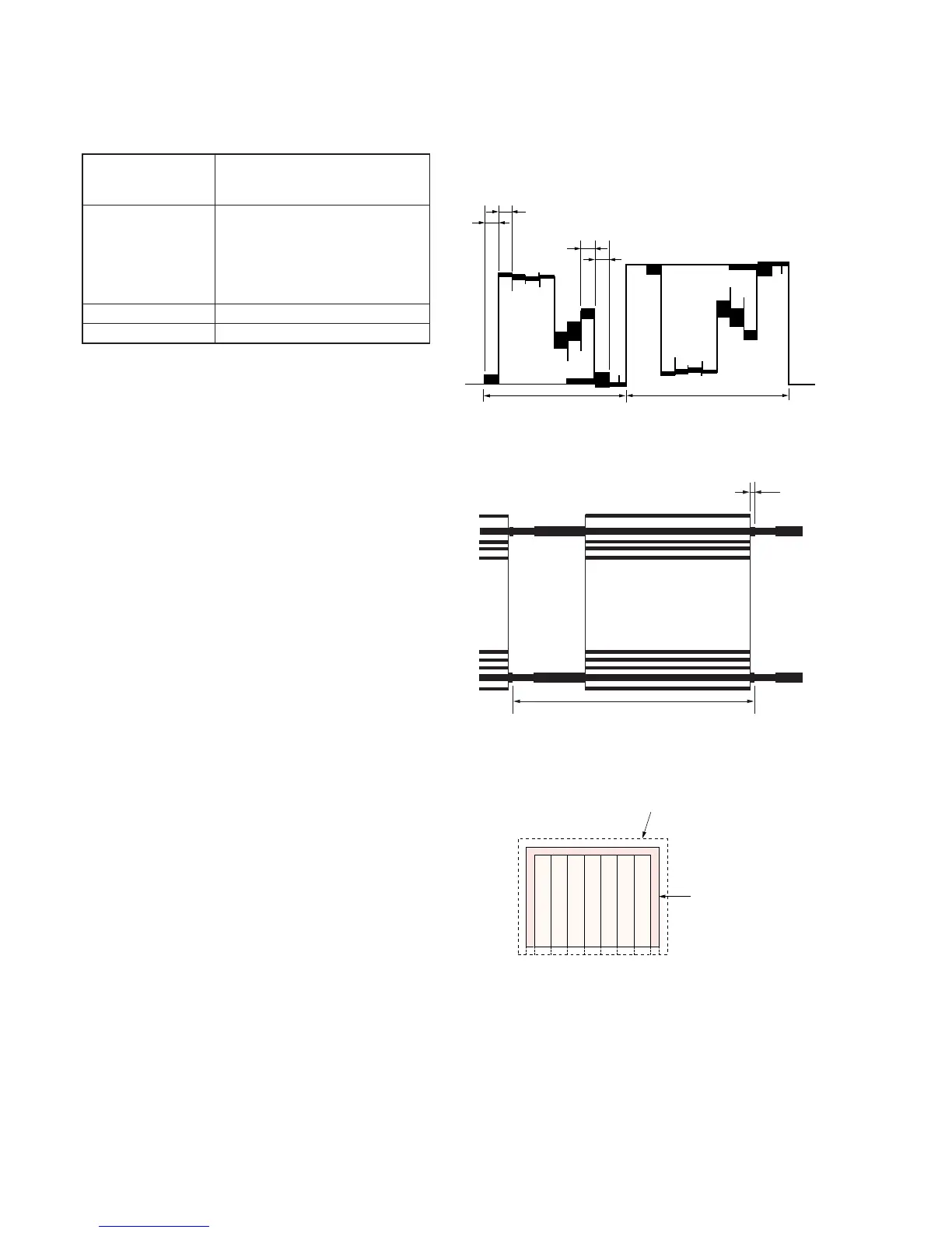
1. Picture Frame Setting
Subject Color bar chart standard picture frame
(1.5m from the front of the protection
glass)
Measurement Point Pin 9 of CN701 (VG) of PK-45 board
External trigger (Horizontal period) :
Pin 8 of CN701 (COM) of PK-45 board
External trigger (Vertical period) :
Pin !¡ of CN701 (LANC IN) of PK-45
board
Measuring Instrument Oscilloscope and LCD screen
Specified Value A=B, C=D, t=0 ± 0.1msec
Setting method:
1) Adjust the focus using the focus ring.
2) Adjust the zoom and the camera direction, and set to the
specified position.
3) Mark the position of the picture frame on the LCD screen, and
adjust the picture frame to this position in following adjustments
using “Color bar chart standard picture frame”.
A
B
A=B
C
D
C=D
H
H
t
V
Electronic beam scanning frame
LCD picture fram
 Loading...