5-17
13. Steady shot adjustment
• Perform the steady shot adjustment only when replacing the
angular velocity sensor. When the microprocessor, circuit, etc.
malfunctions, do not perform this adjustment but check operations
only.
• Record the sensitivity label of the angular velocity sensor (repair
part), including to which side of the board it was attached to, etc.
If it has been attached incorrectly, the image will move up and
down or to the left and right during steady shot operation. Be
sure to take note of this.
Precautions on the Parts Replacement
There are two types of repair parts.
Type A ENC03JA
Type B ENC03JB
Replace the broken sensor with a same type sensor. If replace with
other type parts, the image will vibrate up and down or left and
right during hand-shake correction operations. After replacing, re-
adjust according to the adjusting method after replacement.
Precautions on Angular Velocity Sensor
The sensor incorporates a precision oscillator. Handle it with care
as if it dropped, the balance of the oscillator will be disrupted and
operations will not be performed properly.
Switch setting:
1) Steady Shot (FRONT SW block) ...................................... ON
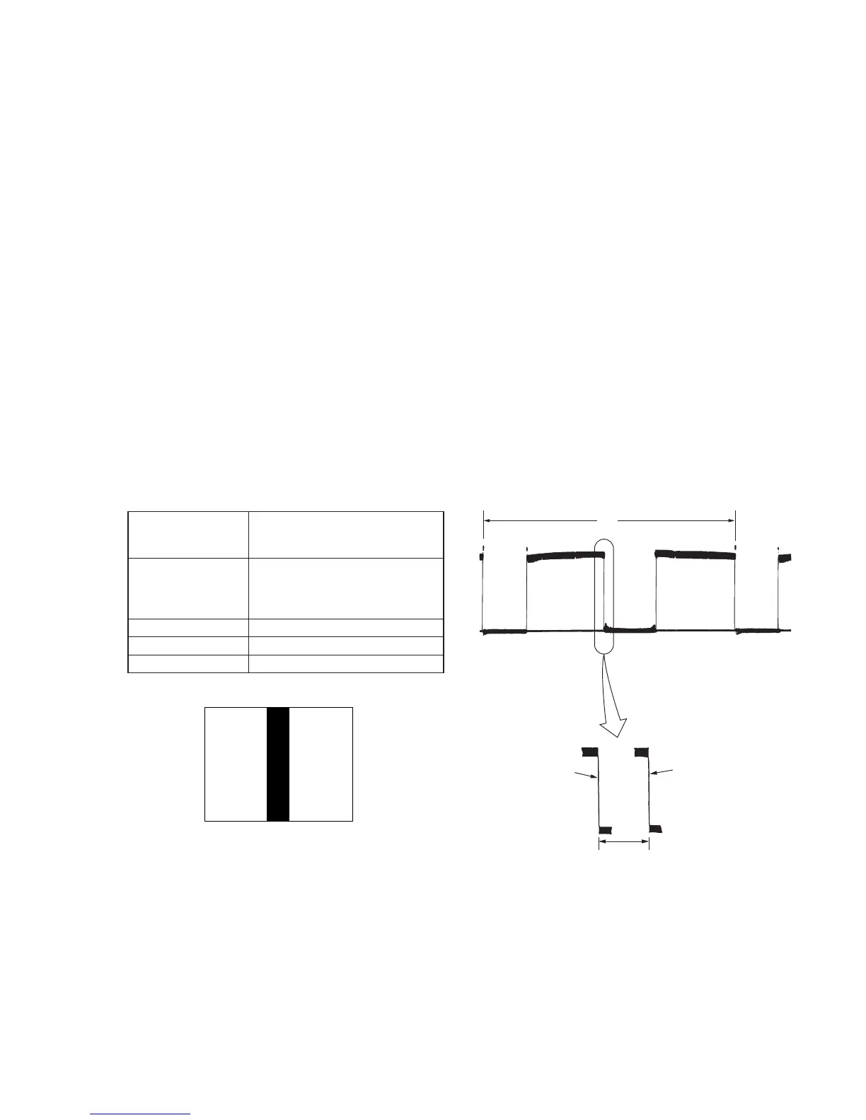
13-1. Steady Shot Adjustment (1)
Subject Pattern A
(1.5m from the front of the protection
glass)
Measurement Point Pin 2 of CN701 of PK-45 board
(PANEL Y)
External trigger: Pin 7 of CN701 of
PK-45 board (HSY)
Measuring Instrument Oscilloscope (H period)
Adjustment Page E
Adjustment Address AD
Fig. 5-1-12.
Adjusting method:
1) Expose pattern A with the zoom TELE end.
2) Adjust the inclination of the camera so that the vertical black
line comes to the center of the screen.
3) Select page: 0, address: 01, and set data: 01.
4) Select page: E, address: BF, set data: 08, and press the pause
button of the adjustment remote commander.
5) Adjust to the falling edge of the waveform with vertical scale
on the oscilloscope. (Oscilloscope is H period).
6) Select page: E, address: BF, set data: 09, and press the pause
button of the adjustment remote commander.
At this time, measure the moving amount t1 (µsec) of the falling
edge of the waveform.
7) Obtain DAD’ using the following equation (decimal calculation).
DAD’ = (4.0/t1)×[1.01/(SE202 sensor sensitivity)]×94
Note: The SE202 sensor sensitivity of the SE-78 board is labeled only
on the repair part.
8) Raise DAD’ to a whole number, convert it to a hexadecimal digit
and take this as DAD. (Refer to Table 5-2-1. “Hexadecimal -
Decimal conversion table” of “5-2. SERVICE MODE”.)
9) Select page: F, address: AD, set data: DAD, and press the pause
button of the adjustment remote commander.
10) Select page: E, address: BF, set data: 08, and press the pause
button.
Procedure after adjustment
1) Select page: 0, address: 01, and set data: 00.
2) Check that the steady shot operation is performed normally.
Fig. 5-1-13.
White
White
Pattern A
A4 size (297mm
×
210mm)
Black
H
t1 (
µ
sec)
Falling edge of
waveform when
data is “09”
Falling edge of
waveform when
data is “08”
 Loading...