EasyManua.ls Logo

Sony RMT-B109A User Manual

Sony RMT-B109A
124 pages
To Next Page IconTo Next Page
To Previous Page IconTo Previous Page
Page #38 background imageLoading...
Page #38 background image
1
A
B
C
D
E
F
G
H
I
J
2
12
13
11
10
98765
43
14
BDP-BX38/S280/S380/S383
4-2
4-2.
FRAME SCHEMATIC DIAGRAM
1
2
3
4
5
1
2
3
4
5
6
7
8
9
1
2
3
4
5
6
7
8
9
1
2
3
4
5
1
2
3
4
5
6
7
8
9
10
11
12
13
14
15
16
17
18
19
20
21
22
23
24
25
26
27
28
29
30
31
32
33
34
35
36
37
38
39
40
41
42
43
44
45
1
2
3
4
5
6
7
8
9
10
11
12
13
14
15
16
17
18
19
20
21
22
23
24
25
26
27
28
29
30
31
32
33
34
35
36
37
38
39
40
41
42
43
44
45
1
2
3
4
5
6
1
2
3
4
5
6
1
2
1
2
3
4
5
6
7
1
2
3
4
5
6
7
8
9
10
11
12
13
14
15
16
17
18
19
20
21
22
23
1
2
3
4
5
1
2
3
4
5
6
7
1
2
3
4
5
6
1234
1
2
3
4
5
6
7
8
9
10
11
12
13
14
15
16
17
18
19
20
21
22
23
1
2
3
4
5
6
7
8
9
10
11
12
13
14
15
16
17
18
19
20
21
22
23
1
2
1
2
3
4
5
6
7
CN2470
CN2460
9P
NOMMOC
W
V
U
DNGF
B
B/
A
A/
CNxxx
9P
COMMON
W
V
U
FGND
B
/B
A
/A
CNxxx
CN1301
45P
CNXXXX
45P
CN1391
6P
MPXOUT1
GND
MPXOUT2
MPXOUT3
GIO13
CN1381
6P
3.3V
RXD
GND
TXD
JIG_MODE0
JIG_MODE1
CN1203
2P
KEY0(POWER)
GND
CN1202
7P
NC
MODE
IF_RXD
IF_TXD
GND
VCC
RESET
CN1204
23P
GND
USB_DP
USB_DM
GND
USB_VBUS2
USB_VBUS1
GND
FLD_STB
FLD_SCK
GND
FLD_DIN
GND
IT_3.3V
LED_WHITE
FLD_PCONT
FR_6V
FR_6V
GND
SIRCS
GND
KEY1(STOP)
KEY2(O/C)
KEY3(Play)
CN1201
5P
GND
MODE
VCC
RESET
NC
CN301
7P
CN1102
6P
CN604
4P
CN701
19P
CN702
23P
KEY3(PLAY)
KEY2(0/C)
KEY1(STOP)
GND
SIRCS
GND
FR_6V
FR_6V
FLD_PCONT
LED_WHITE
IT_3.3V
GND
FLD_DIN
GND
FLD_CLK
FLD_STB
GND
USB_VBUS1
USB_VBUS2
GND
USB_DM
USB_DP
GND
CN331
2P
KEY0(POWER)
GND
CNxxx
7P
LOAD-
LOAD+
GND
TRAY-IN
TRAY-OUT
5P
IF-170
TRAY-IN
TRAY-OUT
LOAD-
5P
LOAD+
GND
1-838-615-11/21
OPT-001
1-838-617-11/21
SPD-001
FFC
LDG-002
1-838-619-11/21
FFC
1-838-618-11/21
FFC
FIM-031
AC OUT
SC_IN(N)
AC_IN(L)
CN101
2P
P/S
SWITCHING REGULATOR831-BMYSSA GNIDAOL DB
BU
DVD_RF-
F
BD_RF-
FD2
SA_A+
A
5.0V
BD_RF+
GND
C
GND
SA_B-
GND
TR
TEST_V
FD1
GND
D
FR2
LDEN
SCLK
GND
THERMO
DVD_RF+
SA_A-
GND
SA_B+
VC_PD
GND
GND
GND
G
MODE_A
SEN_LDD
GND
E
FR1
TD
H
SDIO
GND
8.0V
5V_PD
B
MODE_B(2-->3)
GND
5V_PD
8.0V
BD_RF+
FD2
E
GND
GND
B
MODE_A
GND
FD1
SA_A-
MODE_B(2-->3)
LDEN
BD_RF-
SDIO
SEN_LDD
5.0V
C
THERMO
TEST_V
FR2
SCLK
FR1
DVD_RF-
GND
GND
GND
H
A
DVD_RF+
GND
GND
TR
D
TD
SA_B+
F
SA_A+
G
SA_B-
GND
GND
VC_PD
FFC
IFCON FLASH WRITER
SERVO MONITOR
NISECON
To IF
IFCON DEBUGGER
GND
FE_UNSW12V
FE_GND_M
UNSW12V
UNSW-12
GND
UNSW12V
RXD
GND
NISECON
JIG_MODE1
JIG_MODE0
TXD
3.3V
REAR
SDA
TMDS CLOCK +
TMDS DATA2 -
TMDS CLOCK -
SCL
TMDS DATA0 -
PARTS BODY
+5V POWER
TMDS CLOCK SHIELD
TMDS DATA0 SHIELD
TMDS DATA1 SHIELD
TMDS DATA0 +
HPD
PARTS BODY
DDC/CEC GND
TMDS DATA1 +
TMDS DATA2 +
TMDS DATA1 -
PARTS BODY
TMDS DATA2 SHIELD
CEC
PARTS BODY
RESERVED
HDMI
FL-203
Harness
FLM-001
1-967-315-11/21
FE_UNSW12V
UNSW12V
FE_GND_M
UNSW12V
UNSW-12
GND
GND
Harness
PM-163
1-967-499-11/21
ETHERNET
CN801
VBUSDM
DPGND

Table of Contents

Question and Answer IconNeed help?

Do you have a question about the Sony RMT-B109A and is the answer not in the manual?

Sony RMT-B109A Specifications

General IconGeneral
BrandSony
ModelRMT-B109A
CategoryDVD Player
LanguageEnglish

Summary

SPECIFICATIONS

General Specifications

Core product details like power, dimensions, and operating conditions.

Inputs and Outputs

Details on connectivity ports and signal levels.

SAFETY CHECK-OUT

Safety Check-out Procedure

Steps to ensure safety after repairs.

Leakage Test and Warnings

Procedures for leakage testing and critical safety warnings.

Unleaded Solder Information

Characteristics and handling of unleaded solder.

SECTION 1 SERVICE NOTE

Disc Removal and Optical Device Replacement

Procedures for handling discs and optical components.

Test Disc Operations

Using test discs for functional verification.

Drive Repair and Adjustment

Procedures for drive repair, checking flow, and data adjustment.

SECTION 2 DISASSEMBLY

Disassembly Flow and Component Access

Overall disassembly sequence and accessing major parts.

Front Panel and Board Removal

Steps for removing front panel and specific boards.

SECTION 3 BLOCK DIAGRAMS

Overall System and DSP Block Diagrams

High-level system overview and DSP functional blocks.

Interface and Power Block Diagrams

Diagrams for AV out, USB/Ethernet, and power supply sections.

SECTION 4 SCHEMATIC DIAGRAMS

Schematic Diagram Notes and Frame View

General notes and overall frame schematic.

Specific Board Schematics

Detailed schematics for IF-170, FL-203, and MB-138 boards.

MB-138 Board Waveforms

Diagnostic waveforms for key components.

SECTION 5 PRINTED WIRING BOARDS

Printed Wiring Board Notes and FL-203 Diagram

Notes for PWB diagrams and FL-203 board layout.

IF-170 and MB-138 Board Layouts

Printed wiring board layouts for IF-170 and MB-138.

SECTION 6 IC PIN FUNCTION DESCRIPTION

Main System Control IC Pinout

Detailed pin description for the main control IC.

SECTION 7 SERVICE MODE

Service Mode Overview and Functions

Introduction to service mode and main functions.

Diagnostic Tests (Device, Video, Audio, MIC, HDMI)

Performing various hardware and connectivity tests.

Log Access and Factory Initialization

Displaying logs and resetting player to defaults.

System Information and Version Update

Accessing system details and software updates.

Drive, HDD, Network, and Initialization Operations

Drive/HDD tests, network tests, and initialization.

SECTION 9 TROUBLESHOOTING

Main System and Power Troubleshooting

Overall system and power-related troubleshooting flows.

IFcon and Drive Section Troubleshooting

Flowcharts for IFcon and drive issues.

Audio, Video, and Board Troubleshooting

Flowcharts for audio, video, and board-specific issues.

Connectivity and Device Troubleshooting

Troubleshooting for remote, LED, Ethernet, and USB issues.

SECTION 10 REPAIR PARTS LIST

Exploded Views and Case Section

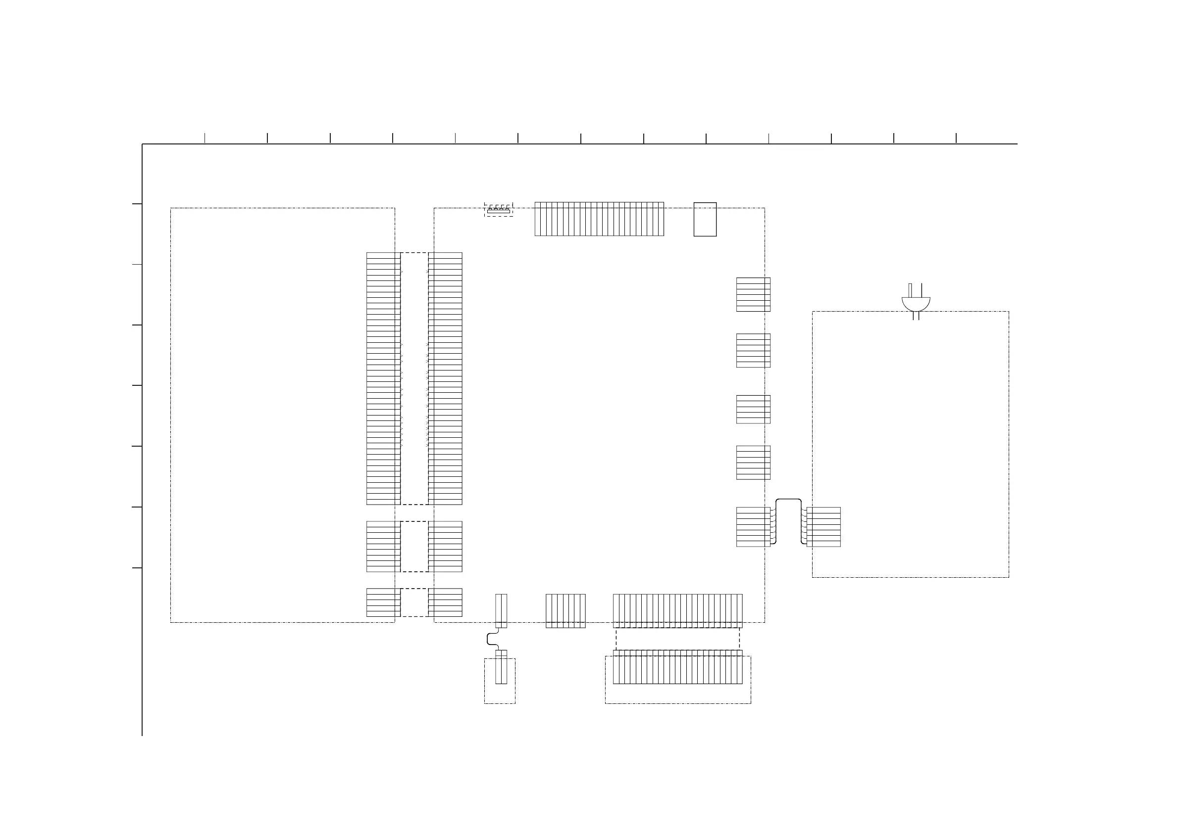
Visual representation of parts and case assembly.

Main Chassis and BD Section Views

Exploded views of the main chassis and BD drive.

Electrical Parts List

Detailed listing of electronic components.

REVISION HISTORY

Document Revision Log

Record of changes and updates to the manual.

Related product manuals