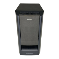
SA-WCT770
9
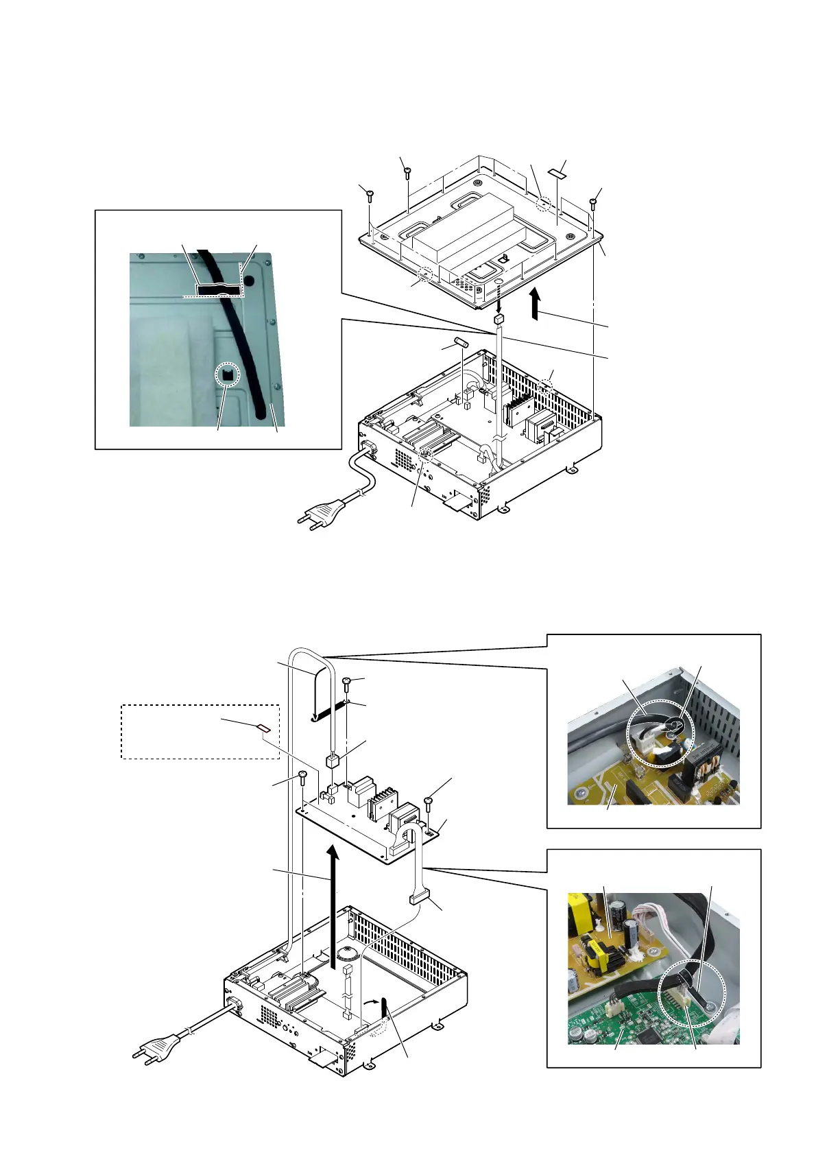
2-7. POWER BOARD
2-6. TOP PLATE BLOCK, FUSE (F900)
guide line
2 eight screws
(BV3)
2 five screws
(BV3)
6 fuse (F900)
2 three screws
(BV3)
1 unweaved cushion
unweaved cushion
4 Draw out the wire.
boss
boss
hole
hole
3 Remove the top plate block
in the direction of the arrow.
hole
5 top plate block
Note:
When installing the top plate
block, make the position of
two holes match two bosses.
top plate block
– Sub AMP block rear view –
:ire VeWWiQJ
5 screw
(BV3 u 8 CU)
0 POWER board
4 connector
(CN114)
8 Remove the POWER
board block in the
direction of the arrow.
clamp (L35)
power cord
POWER board
POWER board
coating clip
SUB MAIN board connector (CN114)
3RZHUFRUGVHWWLQJ
:LUHVHWWLQJ
2 power cord connector
(CN900)
7 clamp (L35)
6 screw
(BV3)
9 label fuse (T.H)
([FHSW86&DQDGLDQ
6 two screws
(BV3)
1 Remove the power cord
from the clamp (L35).
3 Remove two wires from
the coating clip.
–6XE$03EORFNUHDUYLHZ–
Ver. 1.1
 Loading...