HT-S350/SD35
13
Sony CONFIDENTIAL
For Authorized Servicer
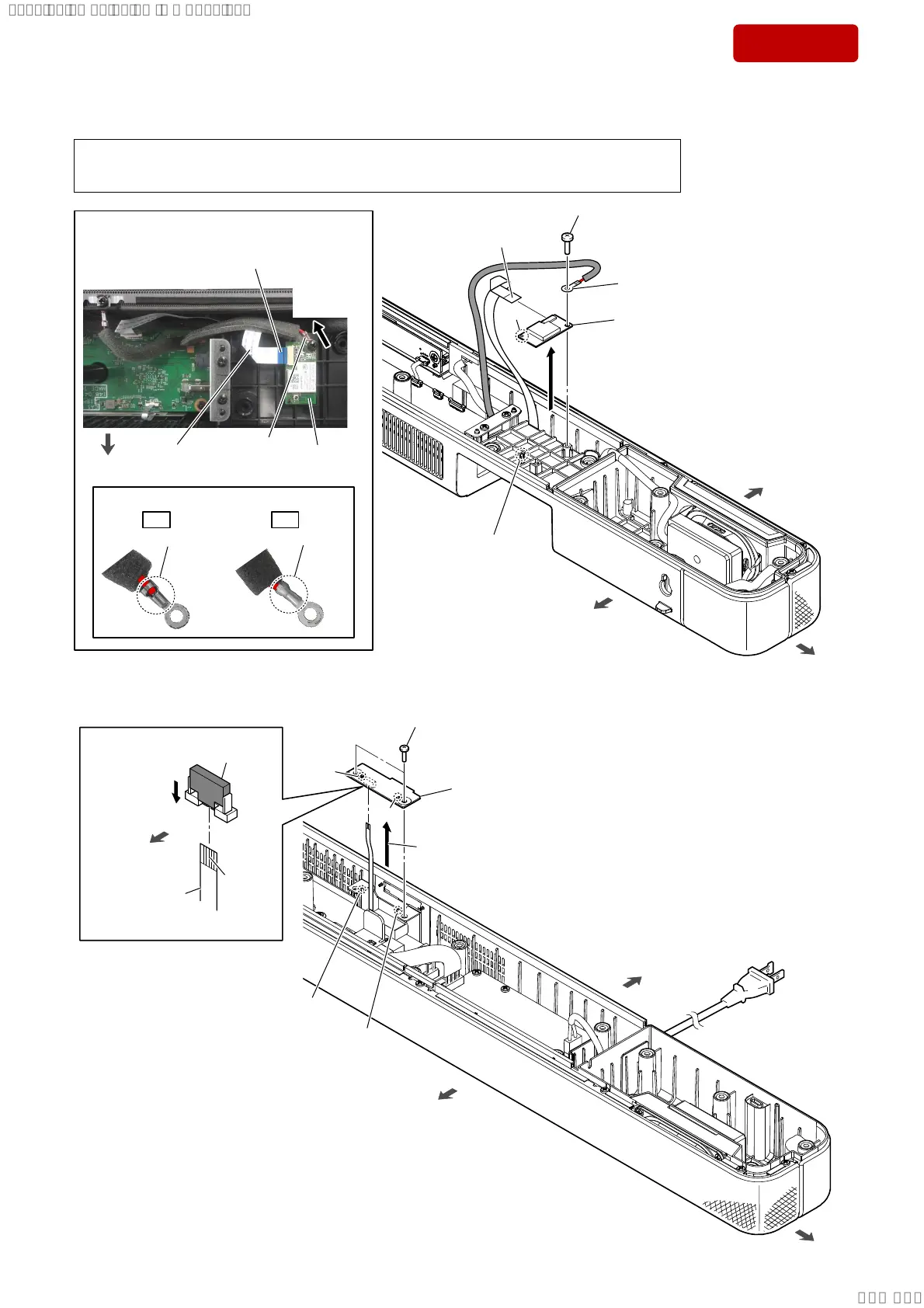
2-5. BT MODULE
OK NG
front side
rear side
left side
hole
• Installation direction for the lug terminal
– Top view –
Caulking is upward. Caulking is downward.
• Wire with lug terminal setting
The opposite side
is terminal side.
2 screw
(BTP3 u 10)
BT
module
wire with
lug terminal
– Top view –
rear side
FFC
(18 core)
1 Draw the FFC (18 core)
out of the connector.
boss
3
wire with lug terminal
4
5
BT module
(See Note 1)
Note 2:
When installing the BT module,
align the boss and hole.
Note 1:
If BT module is replaced with a new part, refer to “RESET METHOD” on page 6, be sure to perform the reset.
Also, after completing the reset, refer to “WIRELESS CONNECTION (LINK) WORK OF BAR SPEAKER
AND THE SUBWOOFER” on page 7, perform the wireless connection of bar speaker and subwoofer.
lug terminal
direction
2-6. IR RP BOARD
front side
rear side
right side
3
Unlock the
connector.
connector
(CN1)
terminal
side
4 Draw the FFC
(6 core) out of
the connector.
1 two screws
(BTP3 u 10)
5
IR PR board
Note:
When installing the IR PR board,
align the two ribs and two holes.
2
Lift up the IR PR board block
in the direction of the arrow.
rib
rib
hole
hole
front side
SYSSET
2019/02/1301:27:25(GMT+09:00)
 Loading...