2121
STR-DA1200ES
STR-DA1200ES
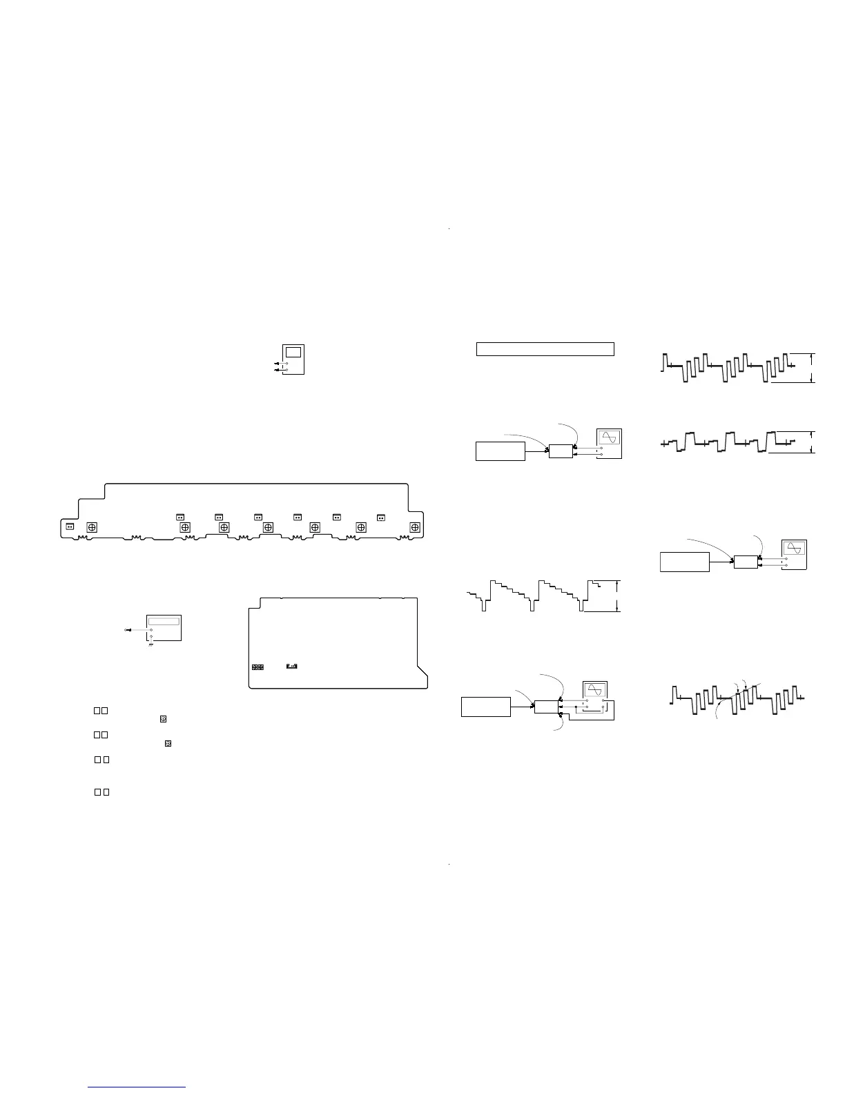
UP CONVERT SIGNAL LEVEL ADJUSTMENT
Enter the test mode
1. In the standby status, press the [POWER] button while pressing
the [2CH] and [TONE MODE] buttons.
2. It enters the test mode, and display as below figure.
1. Y Level Adjustment
Setting:
Procedure:
1. Connect a color pattern generator to the DVD S VIDEO IN
jack (J6902) on the S-VIDEO board, and connect an
oscilloscope to the COMPONENT VIDEO MONITOR OUT
Y jack (J6301) on the VIDEO board.
2. Enter the test mode.
3. Input color bars signal from the color pattern generator.
4. Adjust the [TUNING] dial so that the Vp-p value of waveform
becomes 1 Vp-p.
2. Color Level Adjustment
Setting:
Procedure:
1. Connect a color pattern generator to the DVD S VIDEO IN
jack (J6902) on the S-VIDEO board, and connect an
oscilloscope to the COMPONENT VIDEO MONITOR OUT
P
B
/C
B
/B-Y jack and COMPONENT VIDEO MONITOR OUT
P
R
/C
R
/R-Y jack (J6301) on the VIDEO board .
2. Enter the test mode.
3. Input color bars signal from the color pattern generator.
4. Display two waveforms of C
B
and C
R
simultaneously.
5. Adjust the [INPUT SELECTOR] dial so that the Vp-p value of
waveforms of C
B
and C
R
both may be most set to 0.7V closely.
3. HUE Level Adjustment
Setting:
Procedure:
1. Connect a color pattern generator to the DVD S VIDEO IN
jack (J6902) on the S-VIDEO board, and connect an
oscilloscope to the COMPONENT VIDEO MONITOR OUT
P
B
/C
B
/B-Y jack (J6301) on the VIDEO board.
2. Enter the test mode.
3. Input color bars signal from the color pattern generator.
4. Adjust the [TONE] dial so that the waveform as bellow.
Display
HU[ 7]CON[ 7]COL[ 7]
(AC range)
set
color pattern
generator
color bars 100%
S-VIDEO board
DVD S VIDEO IN jack
(J6902)
VIDEO board
COMPONENT VIDEO
MONITOR OUT
PB/CB/B-Y jack
(J6301)
SECTION 5
ELECTRICAL ADJUSTMENTS
BIAS ALIGNMENT ADJUSTMENT
Note: Afer 10 minutes or more have passed since the power supply was
turned on, this adjustment is done.
Connection
Procedure:
1. Connect a digital voltmeter to the CNP1502 (CNP1552,
CNP1602, CNP1702, CNP1752, CNP1802, CNP1852) on the
BIAS board.
2. Press the [POWER] button to turn on the main power.
3. Adjust the RV1501 (RV1551, RV1601, RV1701, RV1751,
RV1801, RV1851) so that the digital voltmeter reading is 5 mV
to 20 mV.
Adjustment and Connection Location:
+
–
digital voltmeter
CNP1502 (CNP1552, CNP1602, CNP1702, CNP1752, CNP1802, CNP1852) pin
1
CNP1502 (CNP1552, CNP1602, CNP1702, CNP1752, CNP1802, CNP1852) pin
2
CNP1752
RV1751
1
2
– BIAS Board (Component Side) –
1
2
1
2
1
2
1
2
1
2
1
2
RV1701
CNP1702
RV1551 RV1501 RV1601
CNP1502CNP1552 CNP1602 CNP1852 CNP1802
RV1851 RV1801
OSD ADJUSTMENT
Connection
1. Connect a frequency counter to the TP6501 pin 2 on the VIDEO
board.
2. Press the [POWER] button to turn on the main power.
3. Perform the MEMORY CREARING MODE.
4. Press the [MENU] button on the remote commander to display
“Lebel Setting”.
5. Press the V v button on the remote commander to display
“Video Settings” and press the
button on the remote
commander.
6. Press the V v button on the remote commander to display
“COLOR SYSTEM” and press the button on the remote
commander.
7. Press the V v button on the remote commander to select
NTSC.
8. Adjust the CT6503 so that the frequency counter reading is
3.579545 MHz.
9. Press the V v button on the remote commander to select
PAL.
10. Adjust the CT6504 so that the frequency counter reading is
4.433618 MHz.
VIDEO board
TP6501 pin
2
+
–
frequency counte
 Loading...