3
TABLE OF CONTENTS
1. GENERAL
Main unit ................................................................................. 4
Remote button description....................................................... 6
2. DISASSEMBLY
2-1. Case ..................................................................................... 7
2-2. Front Panel Section ............................................................. 8
2-3. Back Panel........................................................................... 8
2-4. Main Board ......................................................................... 9
3. TEST MODE ..................................................................... 10
4. DIAGRAMS
4-1. IC Pin Description............................................................. 11
4-2. Circuit Boards Location .................................................... 13
4-3. Block Diagram – Main Section – ...................................... 15
4-4. Block Diagram – Power Section – .................................... 16
4-5. Printed Wiring Boards – Main Section – ..........................17
4-6. Schematic Diagram – Main Section (1/2) – ...................... 18
4-7. Schematic Diagram – Main Section (2/2) – ...................... 19
4-8. Printed Wiring Boards – Panel Section – .......................... 20
4-9. Schematic Diagram – Panel Section – .............................. 21
4-10. IC Block Diagrams............................................................ 22
5. EXPLODED VIEWS
5-1. Case Section ...................................................................... 23
5-2. Front Panel Section ........................................................... 24
5-3. Chassis Section ................................................................. 25
6. ELECTRICAL PARTS LIST ........................................ 26
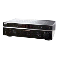
STR-DE197
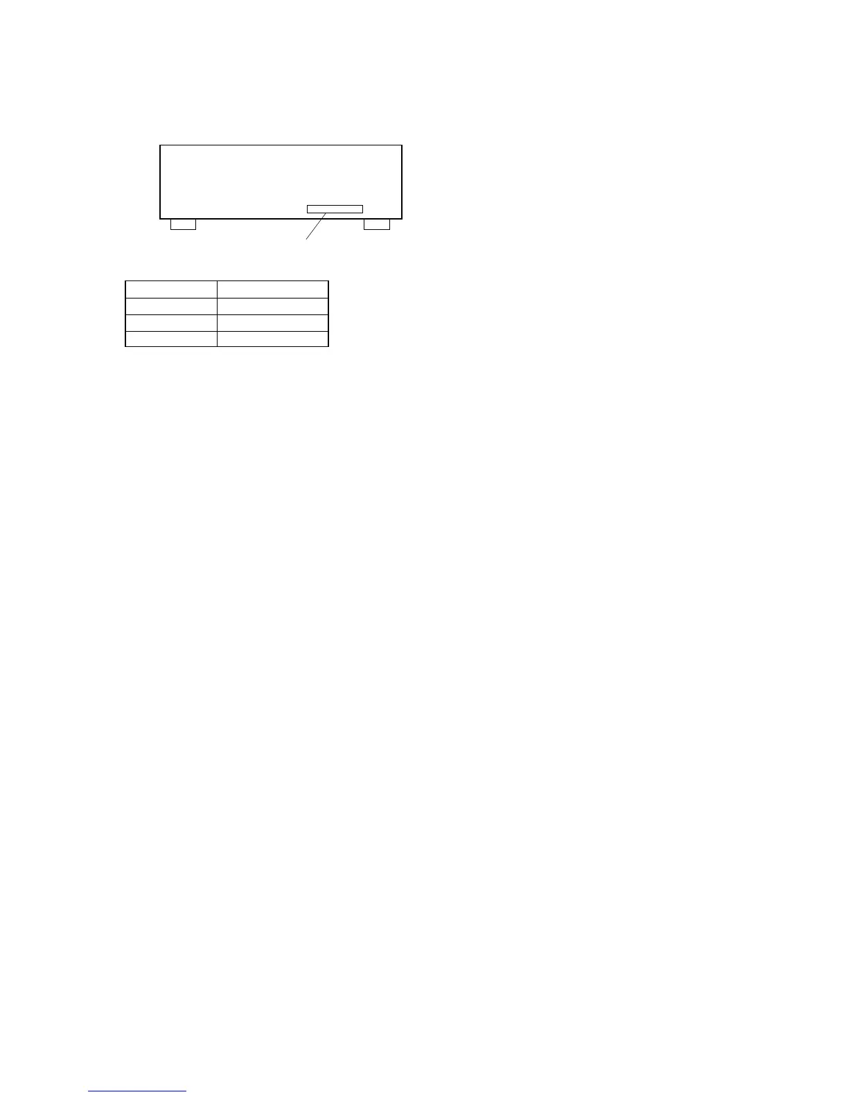
MODEL IDENTIFICATION
— BACK PANEL —
Part No.
MODEL PART No.
US 4-253-299-0s
AEP 4-253-299-1s
CND 4-253-299-3s
•Abbreviation
CND: Canadian model
 Loading...