 Loading...
Do you have a question about the Sony STR-DH720 and is the answer not in the manual?
| Display | VFL |
|---|---|
| Equalizer | Yes |
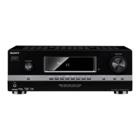
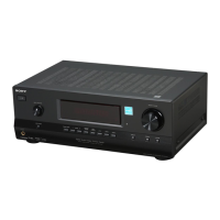
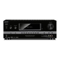
| Product color | Black |
| Audio decoders | Dolby Digital, Dolby Digital EX, Dolby Pro Logic, Dolby Pro Logic II, Dolby Pro Logic IIx, DTS 96/24, DTS Neo:6, DTS-ES (Discrete 6.1), DTS-ES (Matrix 6.1) |
| Apple docking compatibility | Not supported |
| Graphical user interface (GUI) | No |
| Audio output channels | 7.1 channels |
| Power output per channel (1KHz@8 Ohm) | 200 W |
| Power output per channel (20-20KHz@8 Ohm) | 170 W |
| HDMI in | 3 |
| Audio (L/R) in | 5 |
| Digital audio coaxial in | 1 |
| Digital audio optical in | 2 |
| Ethernet LAN (RJ-45) ports | 0 |
| Multichannel audio input type | RCA, Terminals |
| Connectivity technology | Wired |
| Speakers connectivity type | Clamp terminals |
| Wi-Fi | - |
| Supported radio bands | AM, FM |
| Preset stations quantity | 60 |
| Optical drive type | Blu-Ray player |
| Depth | 322 mm |
|---|---|
| Width | 430 mm |
| Height | 157.5 mm |
| Weight | 8000 g |
Details power output and harmonic distortion for US models with 8-ohm loads.
Specifies power requirements based on geographical area.
Outlines the analog frequency response range and tolerance.
Lists input specifications for analog and digital signals.
Provides voltage and impedance for analog audio outputs.
Procedures for performing an AC leakage test on exposed metal parts.
Identifies models and their corresponding part numbers.
Guidelines for replacing chip components, including precautions.
Information on using unleaded solder and its characteristics.
Notice regarding components identified by mark 9 for confidential information.
Procedure for disassembling the main case of the unit.
Procedure for disassembling the D-VIDEO board.
Procedure for disassembling the front panel section.
Procedure for disassembling the back panel section.
Procedure for disassembling the DIGITAL board.
Procedure for disassembling the main board section.
Procedure for disassembling the MAIN board.
Selects the AM channel step for US and Canadian models.
Tests all segments of the vacuum fluorescent display.
Clears preset sound fields, used before returning product.
Displays the software version and destination.
Checks the functionality of each button on the unit.
Swaps signals to all channels for speaker output testing.
Resets all preset contents to default values.
Disables the auto-off function after protector activation.
Details how to access and navigate the history mode.
Explains how to access source or microphone modes.
Steps to update main MCU, video MCU, DSP, and software via USB.
Displays the version number to check for USB updates.
Decides the standard of the video input signal for calibration.
Illustrates the connection setup for video calibration.
Steps to adjust video signals using a color pattern generator.
Steps to adjust video signals using a Blu-ray Disc player.
Checks if FM signals are detected and automatic scanning stops correctly.
Shows the block diagram for the tuner and audio sections.
Provides the schematic diagram for the HEADPHONE board.
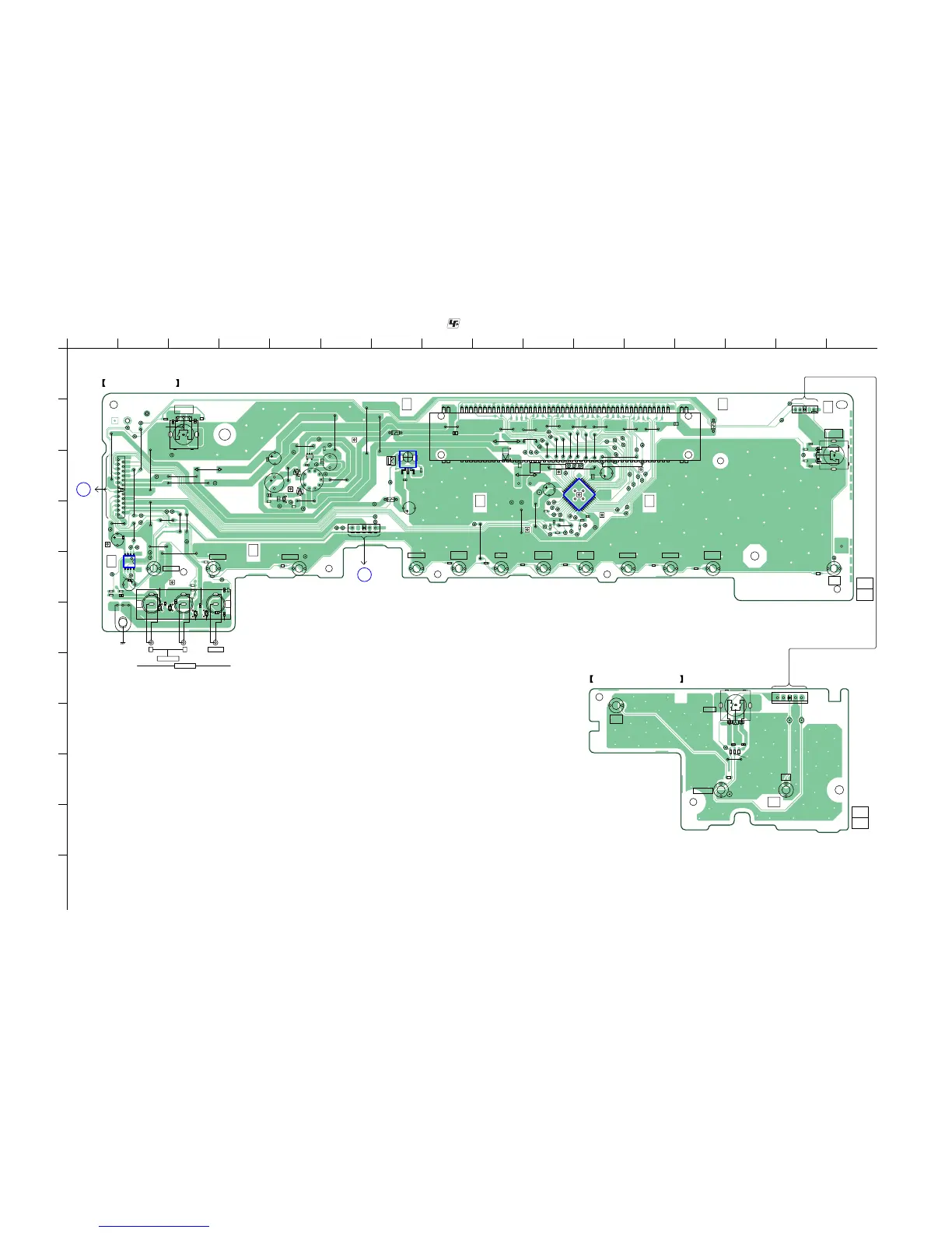
Shows the component layout for the TEMP-SENSOR board.
Provides the schematic diagram for the TEMP-SENSOR board.
Block diagram for IC2006 PCM9211PTR on the DIGITAL board.
Block diagram for IC2032 TC74VHC157FT on the DIGITAL board.
Block diagram for IC2804 TC74VHC157FT on the DIGITAL board.
Block diagram for IC3001 TC74VHC157FT on the D-VIDEO board.
Block diagram for IC2501 WM8768GEDS/R on the DIGITAL board.
Block diagram for IC2303 TC7WHU04FU on the DIGITAL board.
Block diagram for IC4160 TC7WHU04FU on the USB board.
Block diagram for IC2005 TC74VHC08FT on the DIGITAL board.
Block diagram for IC2805 TC74VHC08FT on the DIGITAL board.
Exploded view of the unit's case section with part references.