1111
SECTION 5
DIAGRAMS
5-1. NOTE FOR PRINTED WIRING BOARDS AND SCHEMATIC DIAGRAMS
Note on Printed Wiring Board:
• X : parts extracted from the component side.
• Y : parts extracted from the conductor side.
• x : parts mounted on the conductor side.
• b : Pattern from the side which enables seeing.
(The other layers' patterns are not indicated)
• Indication of transistor.
Note on Schematic Diagram:
• All capacitors are in µF unless otherwise noted. pF: µµF
50 WV or less are not indicated except for electrolytics
and tantalums.
• All resistors are in Ω and
1
/
4
W or less unless otherwise
specified.
•
f
: internal component.
• 2 : nonflammable resistor.
• 5 : fusible resistor.
• C : panel designation.
• U : B+ Line.
• V : B– Line.
• Voltages and waveforms are dc with respect to ground
under no-signal (detuned) conditions.
no mark : TUNER (FM)
• Voltages are taken with a VOM (Input impedance 10 MΩ).
Voltage variations may be noted due to normal produc-
tion tolerances.
• Waveforms are taken with a oscilloscope.
Voltage variations may be noted due to normal produc-
tion tolerances.
• Circled numbers refer to waveforms.
• Signal path.
F : TUNER (FM)
E : TAPE PLAYBACK
G : RECORD
J : CD PLAY
N : MIC INPUT
• Abbreviation
AUS : Australian model
CND : Canadian model
JE : Tourist model
KR : Korean model
Note:
The components identi-
fied by mark 0 or dotted
line with mark 0 are criti-
cal for safety.
Replace only with part
number specified.
Note:
Les composants identifiés par
une marque 0 sont critiques
pour la sécurité.
Ne les remplacer que par une
pièce portant le numéro
spécifié.
B
These are omitted.
CE
Q
B
These are omitted.
CE
Q
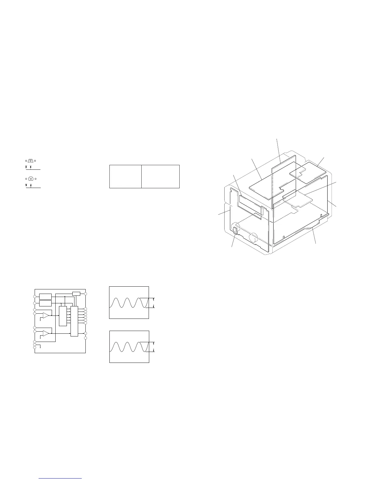
• IC Block Diagram
– MAIN Board –
IC401 BA3830F
• Waveforms
– MAIN Board –
1 IC501 q; (XCIN)
2 IC501 qd (XOUT)
F01
R02
R01
LINE NF
LINE IN
REFERENCE
CURRENT
REFERENCE
CURRENT
RESET
BAND
PASS
FILTER
DET
17
RESET
18
F02
16
F03
15
F04
14
F05
13
F06
12
REC LEVEL
11
VCC
10
4
3
2
1
+
–
REC NF
REC IN
6
RESET C
7
BIAS C
8
GND
9
5
+
–
1.4 Vp-p
32.768 kHz
3 Vp-p
16 MHz
• Circuit Boards Location
SUB TRANS board
(US, Canadian, AEP, UK)
TRANS board
BACK LIGHT board
PANEL baord
R board
PA board
MAIN board
SURROUND AMP board
(NX3)
TUNER pack
MY : Malaysia model
SP : Singapore model
TH : Thai model
 Loading...