Do you have a question about the Sony TA-AV581 and is the answer not in the manual?
| Speaker load impedance | 4 - 16 ohms |
|---|---|
| Input Sensitivity | 200 mV |
| Signal-to-Noise Ratio | 100 dB |
| Output | Speaker Outputs |
| Video Connections | Composite |
| Dimensions | 430 x 330 x 130 mm |
| Power Output | 100 W per channel (8 ohms) |
Details amplifier section power outputs and performance metrics for European models.
Covers power requirements, dimensions, mass, and supplied accessories for the unit.
Instructions for entering and operating the unit's service test modes.
Details on fluorescent tube, LED, AMP, and KEY check modes within the service test.
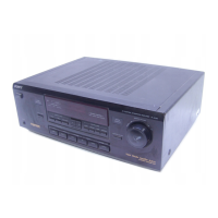
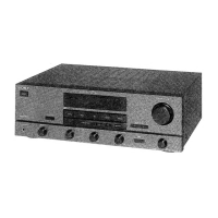
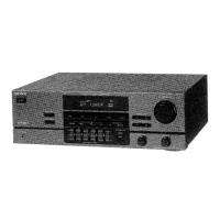
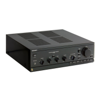
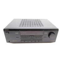
Identifies and describes the function of each button and knob on the front panel.
Identifies speaker terminals, AC outlet, and input/output jacks on the rear panel.
Map showing the physical placement of the main circuit boards within the unit.
Printed wiring board and schematic diagrams for the display section.
Printed wiring boards and schematic diagram for the power section.
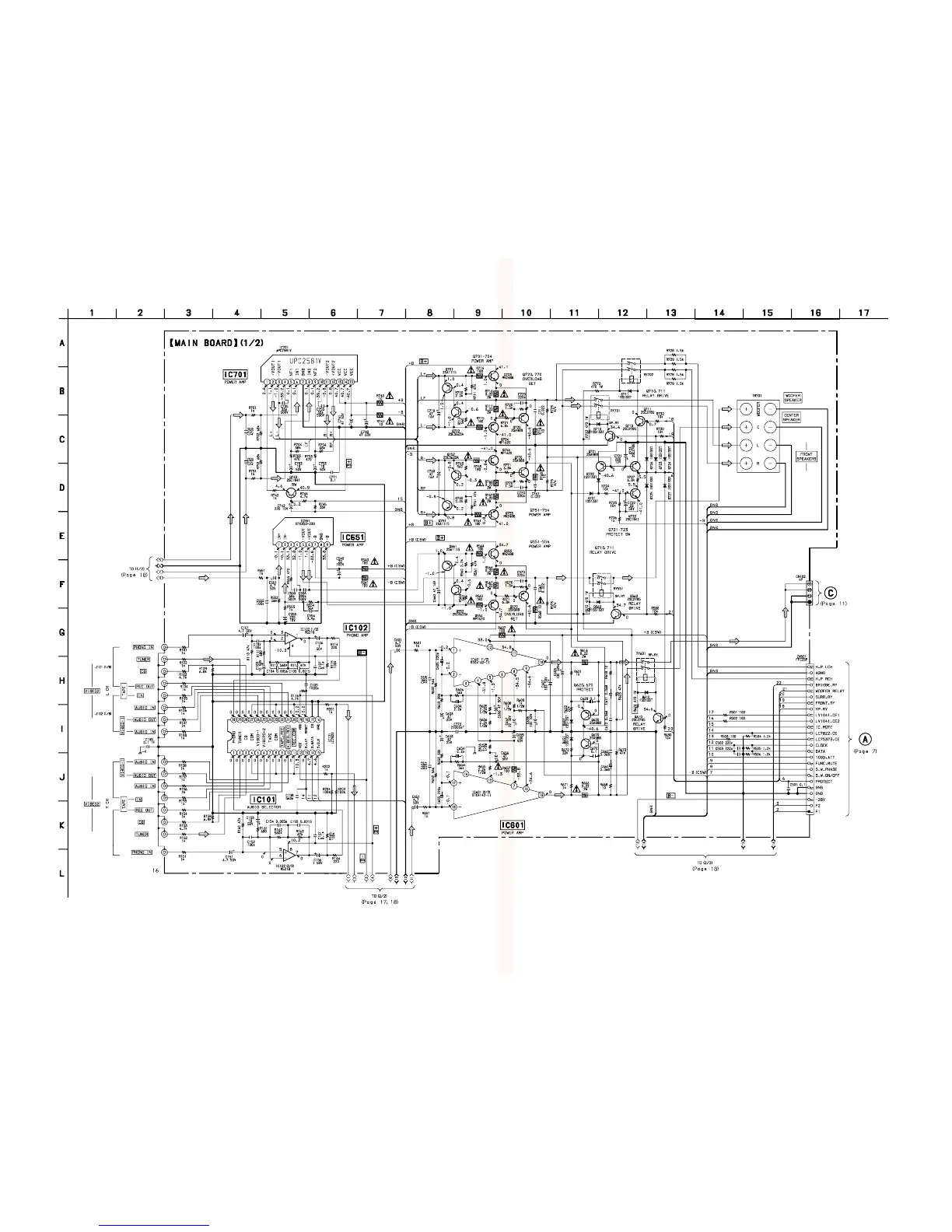
Printed wiring board and schematic diagrams for the main section.
Detailed pinout and function descriptions for key integrated circuits.
Functional block diagrams illustrating the internal operations of key integrated circuits.
Visual breakdown of the front panel components for service and replacement.
Visual breakdown of the chassis and internal mechanical components for service.
List of electronic components for the display section, including part numbers.
List of electronic components for the main board, including part numbers.