— 2 —
SAFETY-RELATED COMPONENT WARNING!!
COMPONENTS IDENTIFIED BY MARK ! OR DOTTED LINE WITH
MARK ! ON THE SCHEMATIC DIAGRAMS AND IN THE PARTS
LIST ARE CRITICAL TO SAFE OPERATION. REPLACE THESE
COMPONENTS WITH SONY PARTS WHOSE PART NUMBERS
APPEAR AS SHOWN IN THIS MANUAL OR IN SUPPLEMENTS
PUBLISHED BY SONY.
SECTION 1
TEST MODE
[Fluorescent Indicator Tube, LED All Lit, and Key Check Mode]
1. When the plug is inserted into the outlet while pressing the
3 CLASSIC button, the fluorescent indicator tube and LED
will light up completely.
2. The mode changes as follows each time the 3 CLASSIC button
and WOOFER ON/OFF button are pressed together after 1.
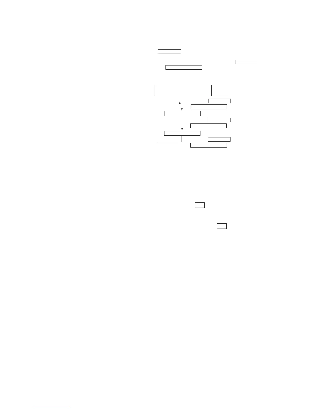
Sequence of Service Modes
Fluorescent Indicator
Tube and LED Check Mode
*1
AMP check mode
*2
•
Press the 3 CLASSIC button and
WOOFER ON/OFF button at the same time.
KEY check mode
*3
•
Press the 3 CLASSIC button and
WOOFER ON/OFF button at the same time.
•
Press the 3 CLASSIC button and
WOOFER ON/OFF button at the same time.
*1 For checking if the fluorescent indicator tube and LED are lit
completely
*2 When the AMP check mode is set, “AMP” is displayed on the
fluorescent indicator tube. As this mode is not used for servicing,
perform step 2 to enter the KEY check mode.
*3 When the KEY check mode is set, “KEY 0”is displayed on the
fluorescent indicator tube. Each press of the button is counted.
(This excludes the | / u button)
When all buttons are pressed, the AMP check mode is set.
Buttons pressed once will not be counted when pressed again.
3. To exit the test mode, press the | / u button
TABLE OF CONTENTS
1. TEST MODE ··································································· 2
2. GENERAL ······································································· 3
3. DIAGRAMS
3-1. Circuit Boads Location ························································ 4
3-2. Printed Wiring Boards – Display Section – ························· 5
3-3. Schematic Diagram – Display Section – ····························· 7
3-4. Printed Wiring Boards – Power Section – ··························· 9
3-5. Schematic Diagram – Power Section – ····························· 11
3-6. Printed Wiring Board – Main Section – ···························· 13
3-7. Schematic Diagram – Main Section (1/2) – ······················ 15
3-8. Schematic Diagram – Main Section (2/2) – ······················ 17
3-9. IC Pin Function Description ·············································· 19
3-10.IC Block Diagrams ···························································· 21
4. EXPLODED VIEWS
4-1. Front Panel Section···························································· 23
4-2. Chassis Section ·································································· 24
5. ELECTRICAL PARTS LIST ···································· 25
 Loading...