— 3 —
— 4 —
SECTION 2
ELECTRICAL ADJUSTMENTS
Bias Adjustment
1. Rotate the semi-fixed resistors (RV501, RV601) for bias
adjustment to the MIN side fully (counterclockwise direc-
tion).
2. Connect a digital voltmeter to CN501 (TP) and CN601
(TP).
1P : ’ side, 2P : ‘ side
3. Turn ON the power button, and adjust RV501 and RV601
so that the digital voltmeter display becomes 22 mV ± 2mV
within 5 seconds.
4. After the adjustment, turn OFF the power button.
SECTION 3
DIAGRAMS
3-1. CIRCUIT BOARDS LOCATION
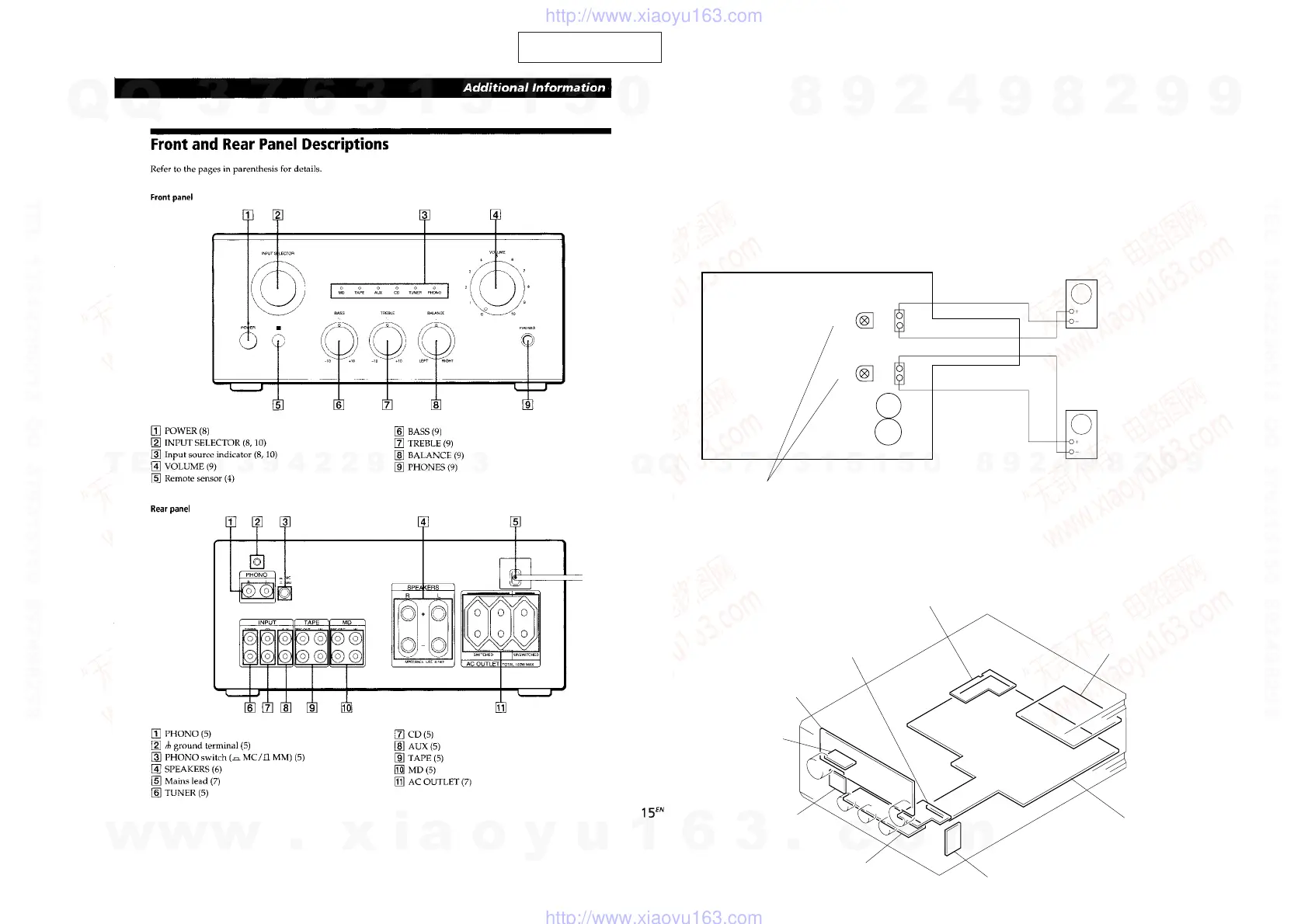
PHONO board
HP board
AC SW board
RM board
AC OUTLET board
VOL board
PANEL board
MAIN board
TONE board
Adjustment Location
[MAIN BOARD] (Component side)
1
2
CN601 (TP)
CN501 (TP)
1
2
RV501
RV601
C801
C802
Bias Adjustment
Digital volt meter
Digital volt meter
SECTION 1
GENERAL
This section is extracted from
instruction manual.
w
w
w
.
x
i
a
o
y
u
1
6
3
.
c
o
m
Q
Q
3
7
6
3
1
5
1
5
0
9
9
2
8
9
4
2
9
8
T
E
L
1
3
9
4
2
2
9
6
5
1
3
9
9
2
8
9
4
2
9
8
0
5
1
5
1
3
6
7
3
Q
Q
TEL 13942296513 QQ 376315150 892498299
TEL 13942296513 QQ 376315150 892498299
http://www.xiaoyu163.com
http://www.xiaoyu163.com
 Loading...