12
The units in this manual contain a self-diagnostic function. If an error occurs, the Smart Core Red LED will automatically begin to flash. The number of times the LED flashes
translates to a probable source of the problem.
A definition of the Smart Core Red LED flash indicators is listed in the instruction manual for the user’s knowledge and reference.
If an error symptom cannot be reproduced, the remote commander can be used to review the failure occurrence data stored in memory to reveal past problems and how often
these problems occur.
DIAGNOSTIC TEST INDICATORS
When an error occurs, the Smart Core Red LED will flash a set number of times to indicate the possible cause of the problem. If there is more than one error, the LED
will identify the first of the problem areas.
Result for all the following diagnostic items are displayed on screen. If the screen displays a “0”, no error has occurred .
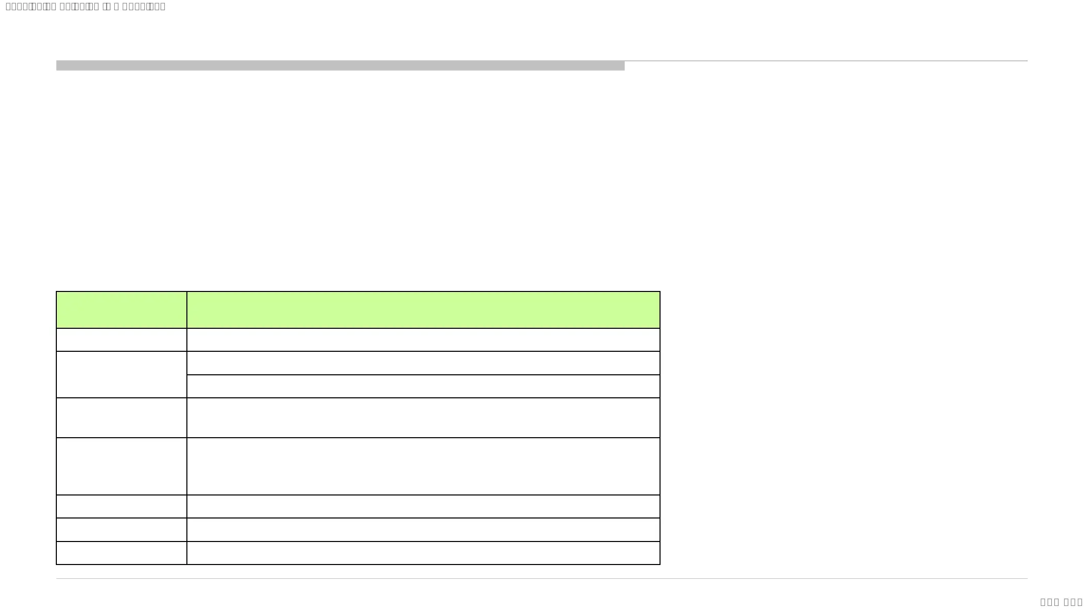
Self Diagnosis Quick Reference (LED blinking)
SELF DIAGNOSIS FUNCTION
Smart Core RED
LED blinking count
Detection Items
2x <B/G> Main 12V over voltage [MAIN_POWER]
3x
<B/G> Main 5.0V failure [DC_ALERT]
<B/S/G> Audio amp. protection [AUD_ERR]
4x
<P/T/B/G>TCON internal error/TCON I2C communication failure [LD_ERR]
<P/T/G/B> EVDD failure [BCM_ERR]
5x
<P/T/G/B> Panel ID EEPROM I2C No ACK
(Also, panel power failure is a suspect) [P_ID_ERR]
<T/B>Data corruption in EEPROM[P_ID_ERR]
6x <P/G/B> EVDD over voltage [BACKLIGHT_ERR]
7x <P/B> Over temperature protection [TEMP_ERR]
8x <B> 4KBE failure (4KBE WDT) [4KBE_ERR]
Notes:
Blue italic: detect at startup sequence only.
<G>: Power supply board, <B>: Main board,
<T>: T-con board, <P>: Panel module, <S>: Speaker
SYSSET
2023/12/2105:31:02(GMT+09:00)
 Loading...