4/12
ST7 USB Low-Speed Evaluation Board
1.4 HARDWARE INSTALLATION
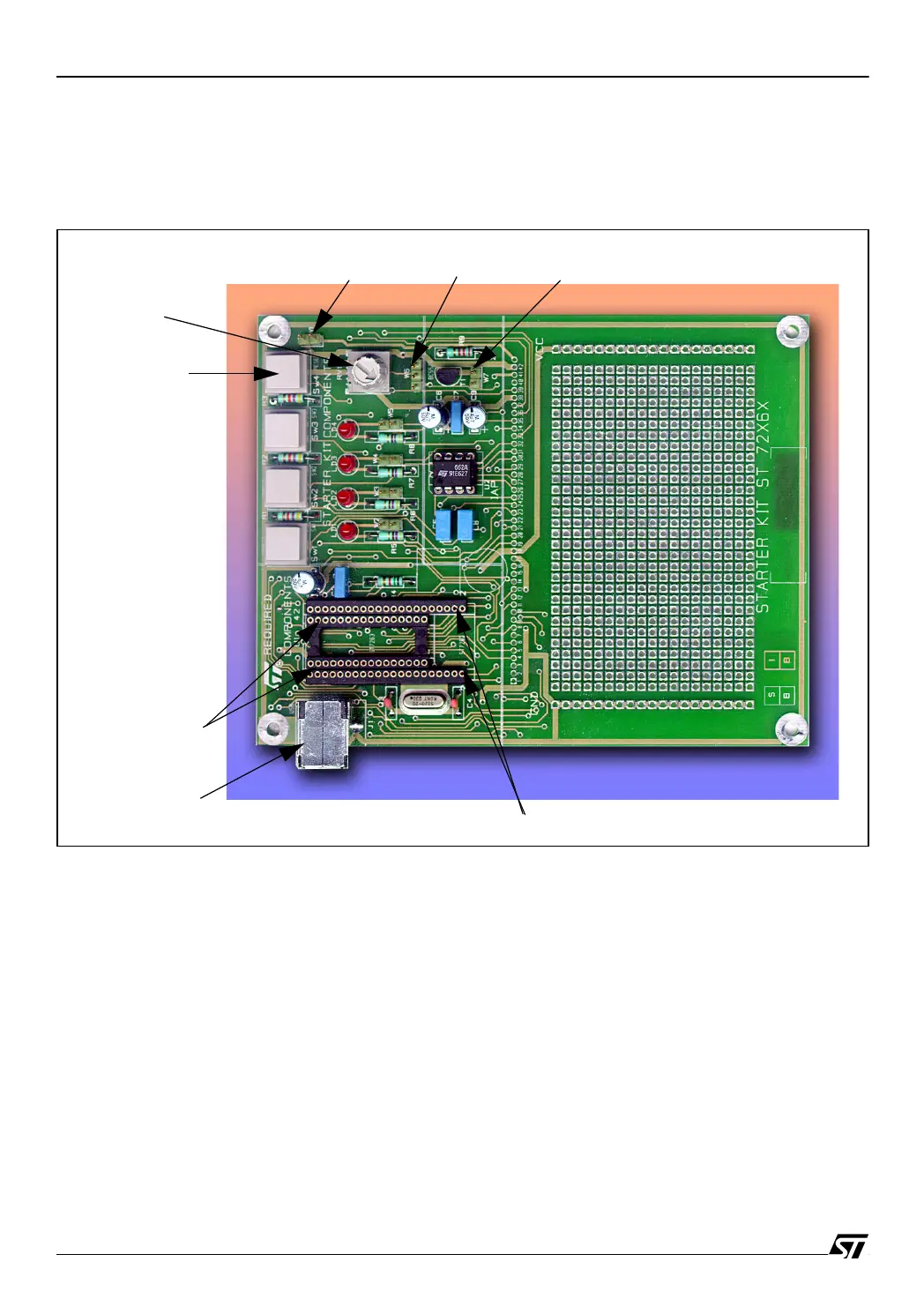
Figure 1 shows the location of the main components of the evaluation board. The schematic
drawing is given in Figure 6.
Figure 1. Evaluation Board Layout
1.4.1 Power Supply
The evaluation board is directly supplied by the USB Connector (Bus powered) and therefore
does not require any external supply. In case the components added on the wire-wrap area
sink more than 500mA, an external power supply must be used.
1.4.2 Jumper Settings
The W1 jumper selects the analog trimmer. When the jumper is removed, the analog trimmer
is disconnected from Ground in order to stop power consumption and to meet the power spec-
ifications of USB suspend state. If A/D conversion is needed for application development, you
can replace this jumper by a switch transistor controlled by an I/O pin.
SW4=Reset
USB Connector
Trimmer
SDIP32 Socket
SDIP42 Socket
& Supply
Jumper W1
Jumper W6
Jumper W7

 Loading...


