UM1724 Rev 14 27/68
UM1724 Hardware layout and configuration
67
All the other solder bridges present on the STM32 Nucleo board are used to configure
several I/Os and power supply pins for compatibility of features and pinout with STM32
supported.
All STM32 Nucleo boards are delivered with the solder-bridges configured according to the
target supported STM32.
6.10 Extension connectors
Figure 10 to Figure 26 show the signals connected by default to ARDUINO
®
Uno V3
connectors (CN5, CN6, CN8, CN9) and to ST morpho connector (CN7 and CN10), for each
STM32 Nucleo board.
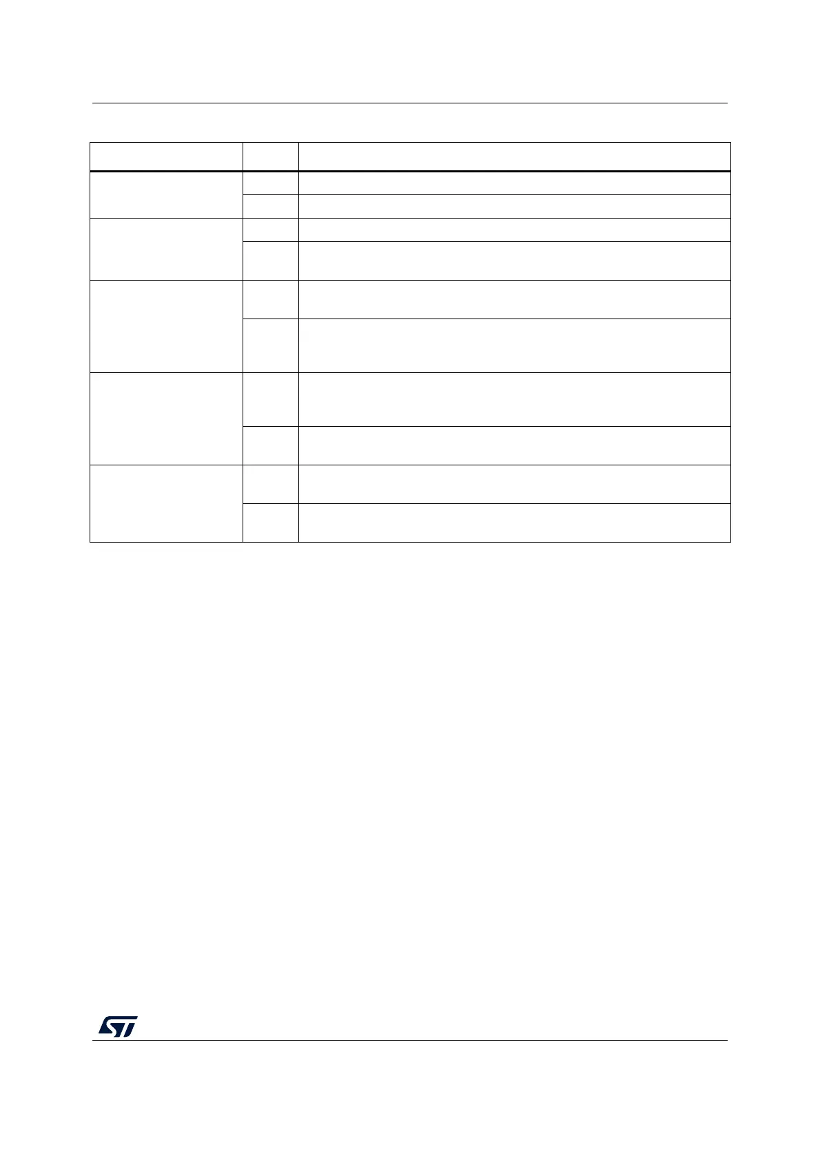
SB45 (VBAT/VLCD)
ON VBAT or VLCD on STM32 is connected to VDD.
OFF VBAT or VLCD on STM32 is not connected to VDD.
SB57 (VDDA/VREF+)
ON VDDA/VREF+ on STM32 is connected to VDD.
OFF
VDDA/VREF+ on STM32 is not connected to VDD and can be provided from
pin 8 of CN5 (Used for external VREF+ provided by
ARDUINO
®
shield)
SB62, SB63 (USART)
OFF
PA2 and PA3 on STM32 are disconnected to D1 and D0 (pin 2 and pin 1) on
ARDUINO
®
connector CN9 and ST morpho connector CN10.
ON
PA2 and PA3 on STM32 are connected to D1 and D0 (pin 2 and pin 1) on
ARDUINO
®
connector CN9 and ST morpho connector CN10 as USART
signals. Thus SB13 and SB14 must be OFF.
SB13, SB14
(ST-LINK-USART)
ON
PA2 and PA3 on STM32F103CBT6 (ST-LINK MCU) are connected to PA3
and PA2 on STM32 to have USART communication between them. Thus
SB61, SB62, and SB63 must be OFF.
OFF
PA2 and PA3 on STM32F103CBT6 (ST-LINK MCU) are disconnected to PA3
and PA2 on STM32.
SB16,SB50(MCO)
(2)
OFF
MCO on STM32F103CBT6 (ST-LINK MCU) are disconnected to
PF0/PD0/PH0 on STM32.
ON
MCO on STM32F103CBT6 (ST-LINK MCU) are connected to PF0/PD0/PH0
on STM32.
1. The default SBx state is shown in bold.
2. The default configuration depends on the board version. Refer to Section 6.7.1: OSC clock supply for details.
3. The default configuration depends on the board version. Refer to Section 6.7.2: OSC 32 kHz clock supply for details.
Table 10. Solder bridges (continued)
Bridge State
(1)
Description
 Loading...


