UM1724 Rev 14 53/68
UM1724 Hardware layout and configuration
67
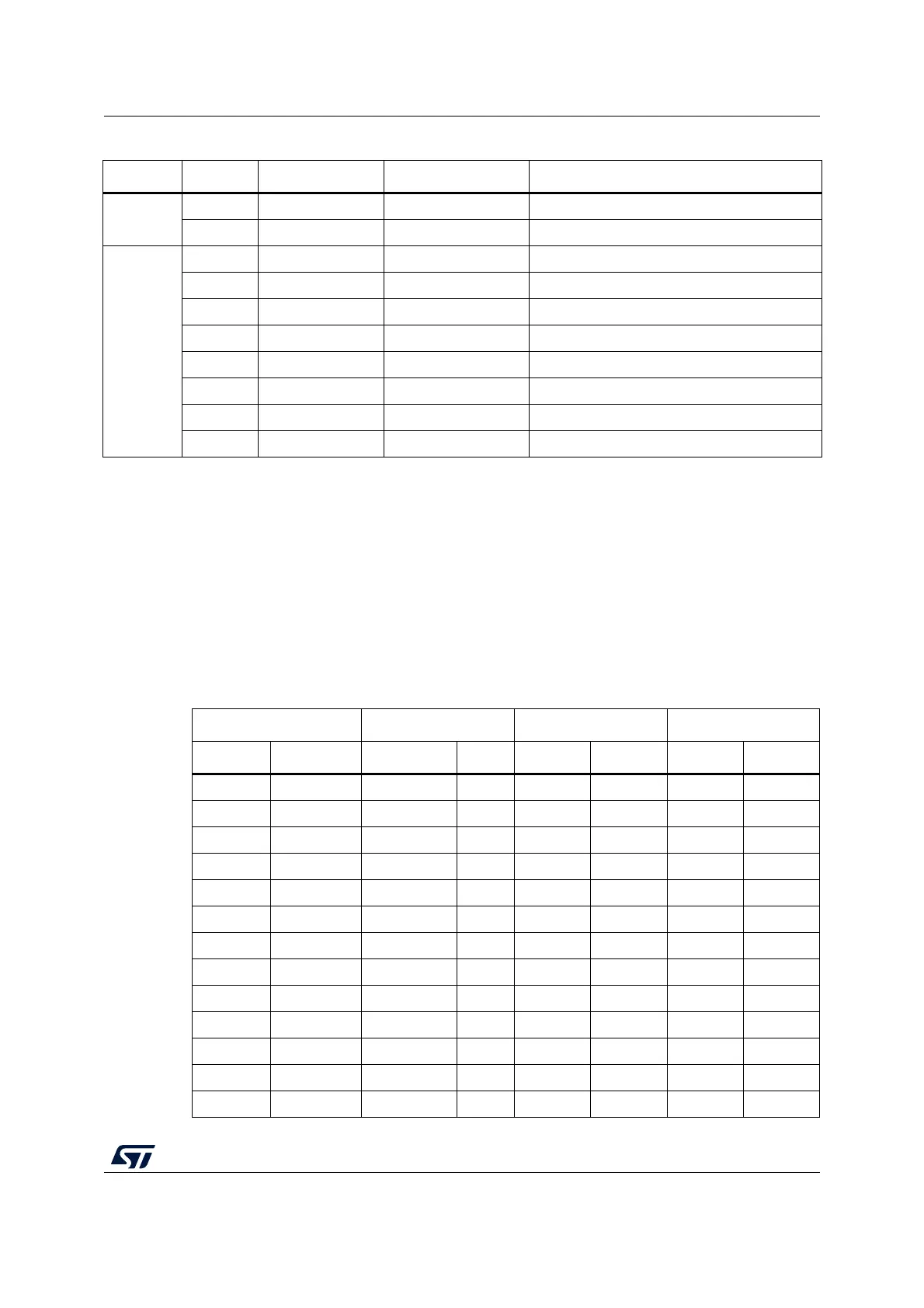
6.12 ST morpho connector
The ST morpho connector consists in male pin headers (CN7 and CN10) accessible on both
sides of the board. They can be used to connect the STM32 Nucleo board to an extension
board or a prototype/wrapping board placed on top or on bottom side of the STM32 Nucleo
board. All signals and power pins of the STM32 are available on ST morpho connector. This
connector can also be probed by an oscilloscope, logical analyzer or voltmeter.
Table 24 to Table 33 show the pin assignments of each STM32 on ST morpho connector.
CN5 digital
2 D9 PC7 TIM3_CH2
1D8 PA9 -
CN9 digital
8D7 PA8 -
7 D6 PB10 TIM2_CH3
6 D5 PB4 TIM3_CH1
5D4 PB5 -
4 D3 PB3 TIM2_CH2
3D2 PA10 -
2 D1 PA2 USART2_TX
1 D0 PA3 USART2_RX
1. Refer to Table 10: Solder bridges for details.
Table 23. ARDUINO
®
connectors on NUCLEO-L476RG (continued)
Connector Pin Pin name STM32 pin Function
Table 24. ST morpho connector on NUCLEO-F030R8
CN7 odd pins CN7 even pins CN10 odd pins CN10 even pins
Pin Name Name Pin Pin Name Name Pin
1 PC10 PC11 2 1 PC9 PC8 2
3 PC12 PD2 4 3 PB8 PC6 4
5 VDD E5V 6 5 PB9 PC5 6
7BOOT0
(1)
GND 8 7 AVDD U5V
(2)
8
9PF6 -109GND-10
11 PF7 IOREF 12 11 PA5 PA12 12
13 PA13 RESET 14 13 PA6 PA11 14
15 PA14 +3.3V 16 15 PA7 PB12 16
17 PA15 +5V 18 17 PB6 PB11 18
19 GND GND 20 19 PC7 GND 20
21 PB7 GND 22 21 PA9 PB2 22
23 PC13
(3)
VIN 24 23 PA8 PB1 24
25 PC14
(3)
- 26 25 PB10 PB15 26
 Loading...


