Hardware layout and configuration UM2324
14/43 UM2324 Rev 4
6.4 Embedded ST-LINK/V2-1
The ST-LINK/V2-1 programming and debugging tool is integrated into the Nucleo.
Compared to ST-LINK/V2 the changes are listed below.
The new features supported on ST-LINK/V2-1:
• USB software re-enumeration
• Virtual COM port interface on USB
• Mass storage interface on USB
• Registers R/W interface on USB (Not available on Nucleo)
• USB power management request for more than 100 mA power on USB
The features no more supported on ST-LINK/V2-1:
• SWIM interface
• Minimum application voltage supported by Nucleo limited to 3V
• Standalone version doesn't exist (only Nucleo and future discovery support V2-1)
For all general information concerning debugging and programming features common
between V2 and V2-1 refer to ST-LINK/V2 user manual (UM1075).
The embedded ST-LINK/V2-1 is usable in two different ways according to the jumper states
(Refer to
Table 5):
• Program/debug the STM32 on board,
• Program/debug an STM32 in an external application board using a cable connected to
the SWD connector.
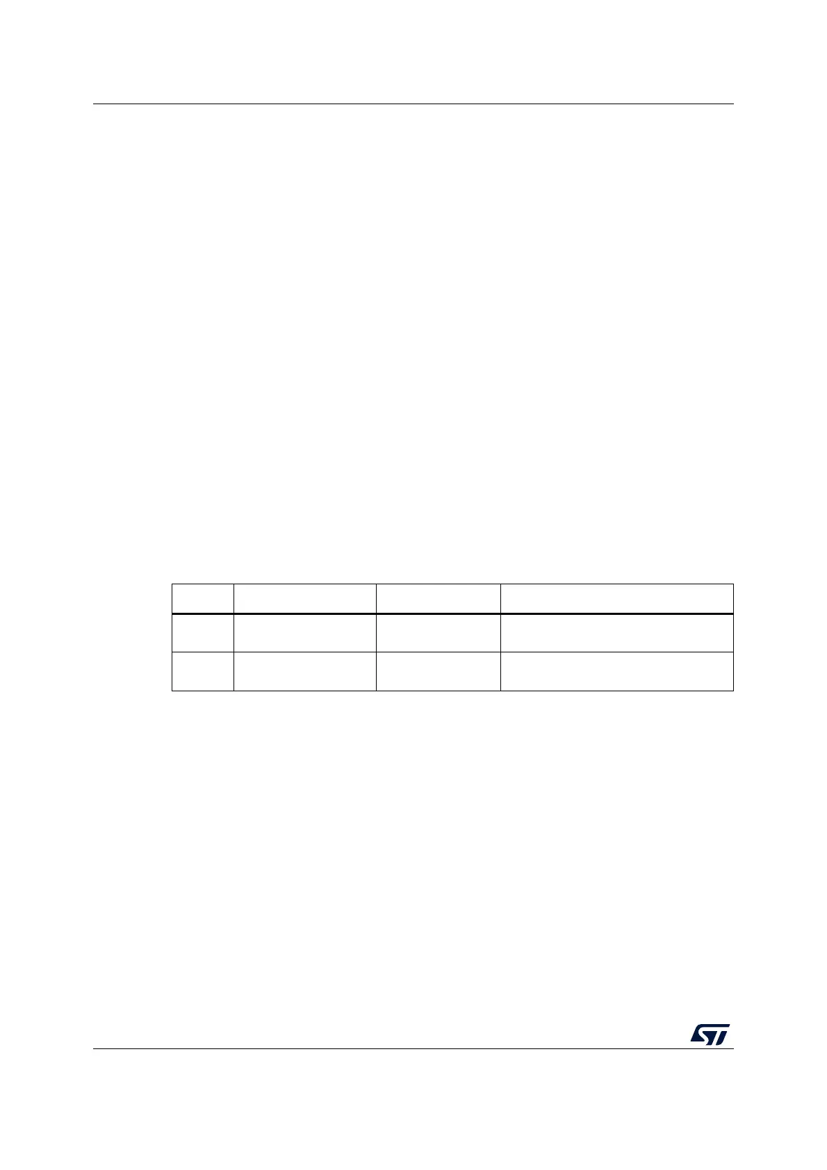
Table 5. ST-LINK jumper configuration
CN Definition Default position Comment
CN4 T_SWCLK / T_SWDIO ON [1-2] ON[3-4]
ST-LINK/V2-1 functions enabled for on-
board programming (default)
CN4 T_SWCLK / T_SWDIO OFF [1-2] OFF[3-4]
ST-LINK/V2-1 functions enabled from
external connector (SWD supported)

 Loading...


