UM2324 Rev 4 25/43
UM2324 Hardware layout and configuration
42
6.10 LEDs
Four LEDs are available on the STM32 Nucleo-64 board. The four LEDs are located on the
top side of the board.
1. LD1 COM: LD1 is a bi-colored LED. the LD1 default status is red. LD1 turns to green to
indicate that communication is in progress between the PC and the ST-LINK/V2-1 as
follow:
– Slow blinking red and off: at power-on before USB initialization
– Fast blinking red and off: after the first correct communication between the PC and
the STLINK/V2-1 (enumeration)
– Red LED on: when initialization between the PC and the ST-LINK/V2-1 is
successfully ended
– Green LED on: after successful STM32 communication initialization
– Blinking red and green: during communication with STM32
– Green on: communication well ended
– Orange on: communication ended with failure
2. LD2: 5V_USB_CHG: this red LED is ON when overcurrent is detected on USB VBUS.
The LED gives the information that more than 500
mA is requested on VBUS. In this
case, it is recommended to supply the board with E5V, VIN, or in USB_CHARGER
mode.
3. LD3: 5V_PWR: this green LED is ON when the STM32 Nucleo-64 board is powered by
a 5
V source.
4. LD4 USER: this green LED is a user LED connected to ARDUINO
®
signal D13
corresponding to STM32 I/O PA5. To light the LED a high-logic state ‘1’ has to be
written in the corresponding GPIO. A transistor is used to drive the LED when the I/O
voltage is 1.8
V. LD4 consumption does not impact the VDD STM32 power
measurement, since LD4 is isolated from it.
6.11 Push-buttons
• B1 USER: User and Wake-Up button connected to the I/O PC13 (Pin 3) of the STM32
Microcontroller.
• B2 RESET: Pushbutton connected to NRST is used to RESET the STM32
Microcontroller.
The blue and black plastic hats placed on these pushbuttons are removable if necessary
when a shield or an application board is plugged on top of Nucleo. This avoids pressure on
the buttons and consequently a possible permanent Target MCU RESET.
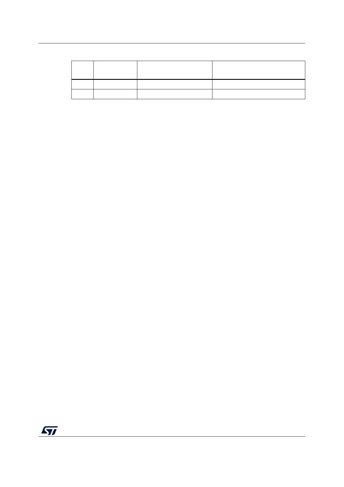
Table 8. UART2 pins
Pin
name
Function
Virtual COM port
(default
configuration)
ST morpho connection
PA2 UART2 TX SB16 ON SB16 OFF
PA3 UART2 RX SB18 ON SB18 OFF

 Loading...


