Solder
bridge
Description
SB4
PC15 is connected to 32-kHz crystal when SB4 is OFF (Default setting).
PC15 is connected to extension connector CN7 when SB4 is ON. In such case R17 must be removed to avoid
disturbance due to the 32-kHz quartz.
Note: For Ethernet clock and jumper JP5 configuration refer to Section Ethernet.
6.6
Reset sources
The reset signal of STM32H7x7I-EVAL Evaluation board is low active and the reset sources include:
• Reset button B1
• Debugging tools from JTAG/SWD connector CN9 and ETM trace connector CN8
• Daughterboard from CN6
• Embedded STLINK-V3E
• RS232 connector CN2 for ISP.
Note: The jumper JP6 has to be ON for RESET handled by pin 8 of RS232 connector CN2 (CTS signal).
6.7
Boot option
The STM32H7x7I-EVAL Evaluation board can boot from:
• Embedded user Flash
• System memory with boot loader for ISP
• Embedded SRAM for debugging
The boot option is configured by setting the switch SW1 (BOOT) and the boot base address programmed in the
BOOT_ADD0 and BOOT_ADD1 option bytes. The BOOT can be also configured through the RS232 connector
CN2.
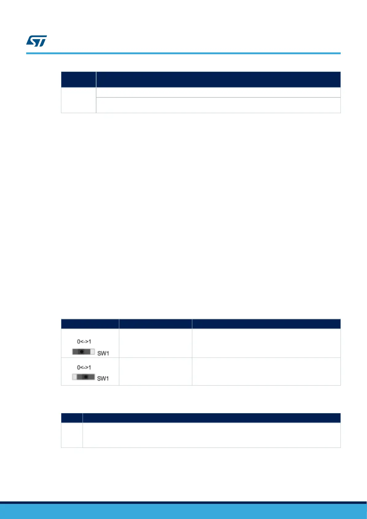
Table 8. Boot selection switch
Switch configuration Boot address option bytes Boot space
(Default setting)
BOOT_ADD0 [15:0]
CPU boot address defined by user option byte
BOOT_ADD0[15:0]
ST programmed value: Flash at 0x0800 0000.
BOOT_ADD1
[15:0]
CPU boot address defined by user option byte
BOOT_ADD1[15:0]
ST programmed value: System boot loader at 0x0000 0000.
Table 9. Boot related jumpers
Jumper
Description
JP3
The Bootloader_BOOT0 is managed by pin 6 of connector CN2 (RS232 DSR signal) when JP3 is ON. This
configuration is used for boot-loader application only.
Default Setting: OFF
UM2525
Reset sources
UM2525 - Rev 3
page 15/69

 Loading...


