7.9 Power connector CN10
The STM32H7x7I-EVAL Evaluation board can be powered from a DC 5 V power supply through the external
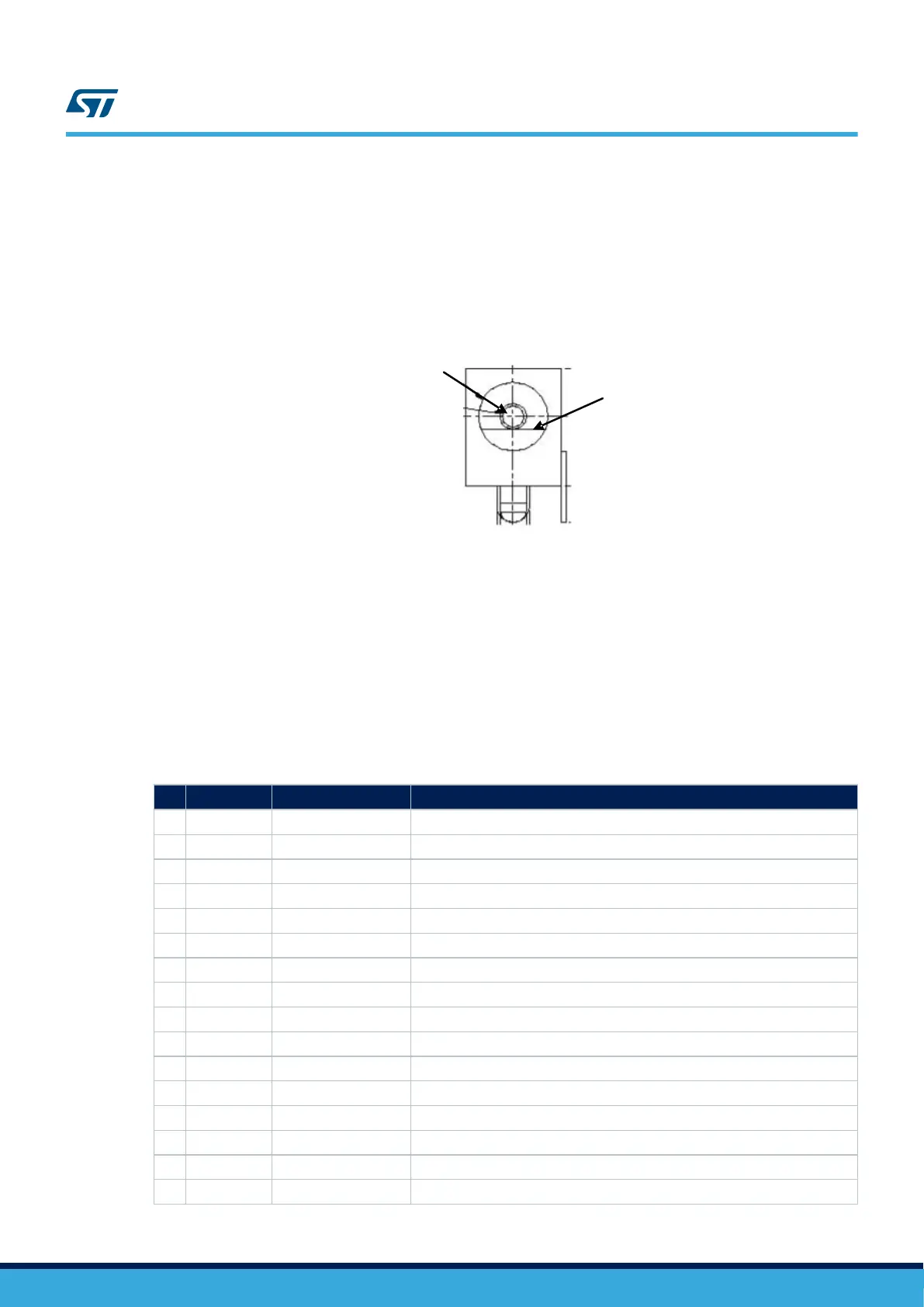
power supply jack (CN10) shown in Figure 13. Power supply connector CN10 (front view). The central pin of
CN10 must be positive.
Figure 12. Power supply connector CN10 (front view)
DC +5V
GND
7.10 Memory connector CN11 and CN12
Two 40-pin male headers CN11 and CN12 are used to connect with memory daughterboard.
All GPIOs are connected on the extension connectors CN6 and CN7, but the GPIOs which are used for FMC
memory signals, are connected on CN11 and CN12.
The space between these two connectors is defined as a standard that allows to develop common
daughterboard. The standard width between CN11 pin1 and CN12 pin1 is 1914 mils (48.62 mm). For details on
signals assignment refer to Table 27. Memory connector CN11 and Table 28. Memory connector CN12.
Table 27. Memory connector CN11
Pin Description Alternative function How to disconnect with function block on STM32H7x7I-EVAL board
1 PH6 SDNE1 -
3 PF13 A7 -
5 PF12 A6 -
7 PG1 A11 -
9 GND - -
11 PE7 D4 -
13 PE10 D7 -
15 PE12 D9 -
17 PE15 D12 -
19 PE13 D10 -
21 PD11 A16 -
23 PD12 A17 -
25 PG5 A15/BA1 -
27 PH11 D19 -
29 GND - -
31 PD13 A18 -
UM2525
Power connector CN10
UM2525 - Rev 3
page 29/69

 Loading...


