Supplying power to the X-NUCLEO-LPM01A UM2243
14/41 UM2243 Rev 2
(USB FS over-current LED) lights up until the over current disappears (see Figure 3: X-
NUCLEO-LPM01A layout top view to locate LD5).
Figure 5. JP3 (USB setting)
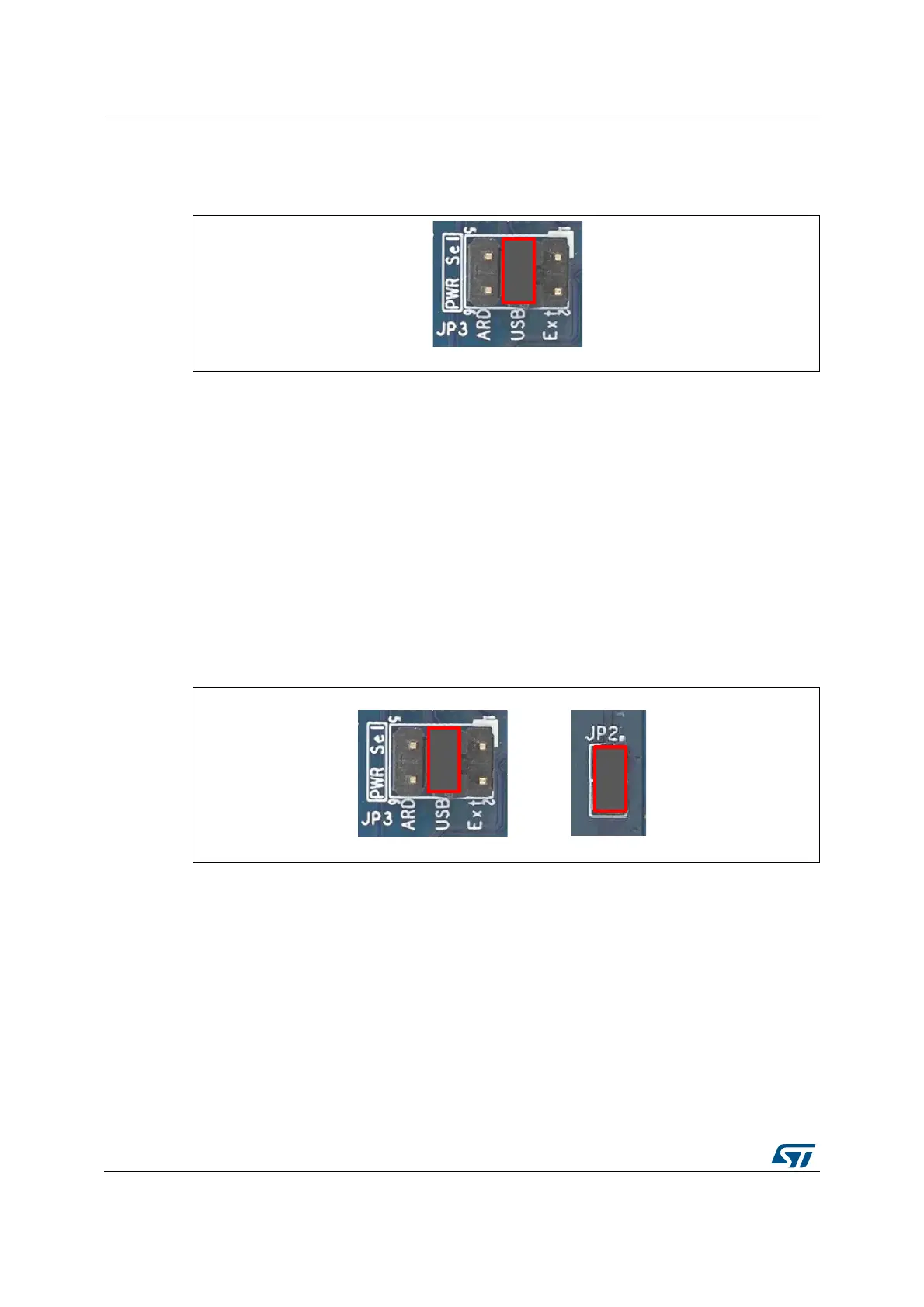
7.2 Power source from a USB charger
A jumper should be inserted in the 'USB' position of JP3 and an additional jumper should be
inserted in JP2 as shown in Figure 6: JP3 and JP2 (USB charger setting).
A USB charger (5 V DC 500 mA minimum) should be connected to the USB FS micro-B
con
nector, CN5. As JP2 is closed, X-NUCLEO-LPM01A peripherals are supplied (and the
target board can be supplied) from USB connector, CN5, regardless of whether or not USB
enumeration succeed.
If an abnormal current higher than 600 mA is drawn by the X-NUCLEO-LPM01A from USB
con
nector CN5, an embedded current protection clamps the current and an LED (LD5, USB
FS over-current LED) lights up until the over current is removed. (See Figure 3: X-NUCLEO-
LPM01A layout top view to locate LD5).
Figure 6. JP3 and JP2 (USB charger setting)
Note: It is not recommended to connect a USB host port from a PC when JP2 is closed, as the X-
NUCLEO-LPM01A supplies power to its peripherals regardless of whether or not the USB
port of the PC is able to provide 500 mA on VBUS as the USB enumeration result is
ig
nored.

 Loading...

