Power supply connections of a target board UM2243
18/41 UM2243 Rev 2
Note: For measurements, jumper JP1 should be always in the ‘normal’, and not in the ‘test’
position. Otherwise it may impact the current measurements results.
Note: As shown in Figure 2: Hardware block diagram, inserting a jumper in the JP4 ‘decoup’
position adds a 2.2 µF decoupling capacitance on the power output voltage (VOUT). It is
recommended
to keep JP4 jumper inserted most of the time to avoid X-NUCLEO-LPM01A
dynamic measurement oscillation, especially when the target board has a decoupling
capacitance of less than 1 µF on its input power supply path.
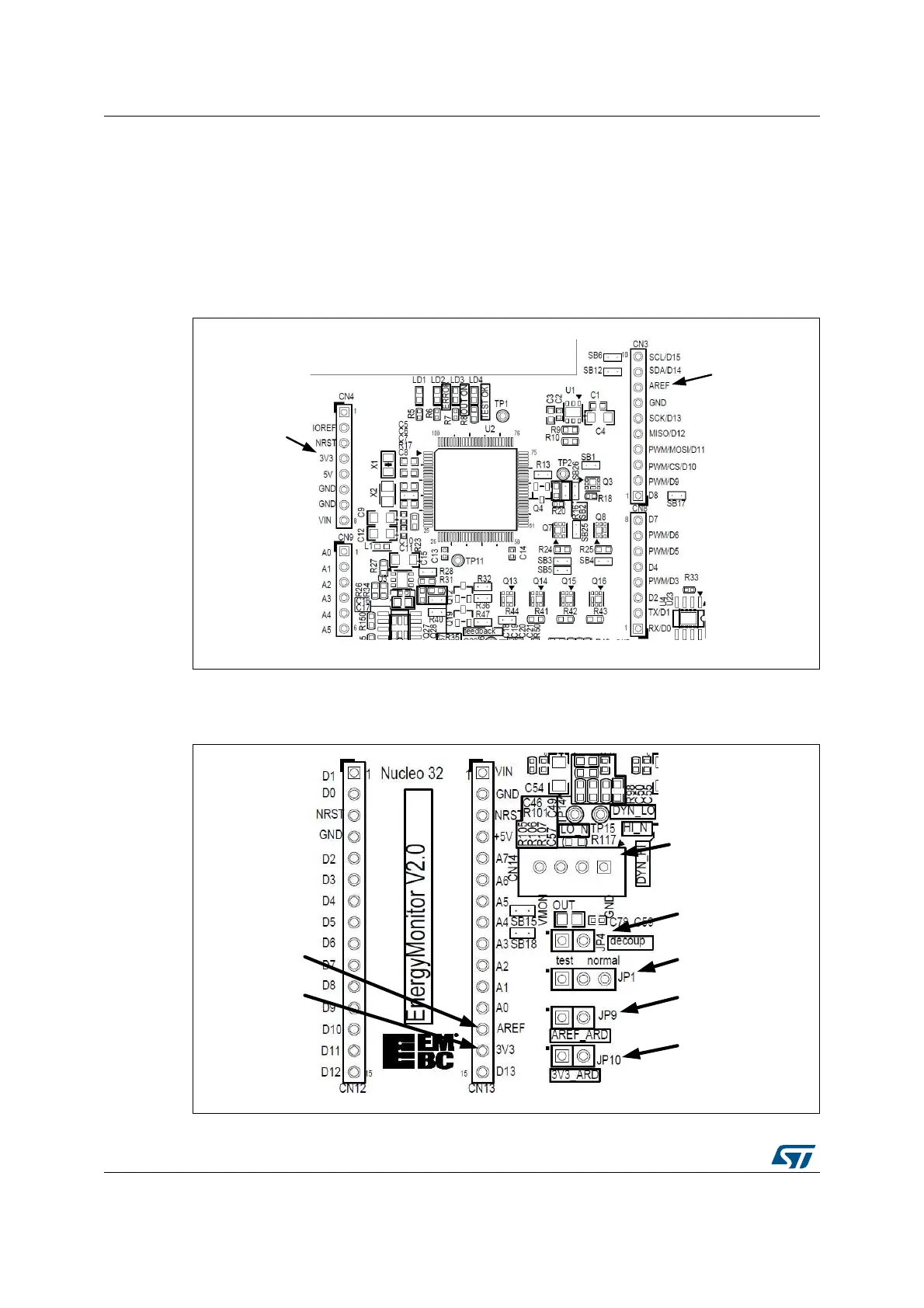
Figure 10. Pins AREF and 3V3 of Arduino Uno connectors CN4 and CN3
06Y9
Z&ŽƵƚƉƵƚ
ϯsϯŽƵƚƉƵƚ
Figure 11. Pins AREF and 3V3 of Arduino Nano connectors, output connector CN14
and
jumpers JP1, JP9, JP10, JP4
06Y9
ĂƐŝĐĐŽŶŶĞĐƚŽƌ
Eϭϰ
ϯsϯŽƵƚƉƵƚ
ϭϮϯϰ
:Wϰ
:Wϭ
:Wϵ
:WϭϬ
Z&ŽƵƚƉƵƚ

 Loading...

