30 Series 4180 Powerhead
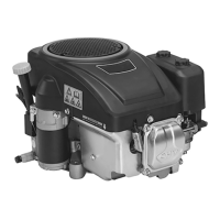
Multi-part system
: Carefully pry the tab (1) of the
connector upwards; take care not
to damage the fuel tank.
1
: Pull the connector (1) with hoses
(2 and 3), molded hose (4) and
pickup body out of the tank.
All systems
1
2
3
4
5
: Pull the pickup body (1) off the
molded hose (2).
– Replace damaged parts. Make
sure the new fuel supply system
matches the machine’s fuel tank.
Reassemble in the reverse
sequence.
– Attach pickup body with molded
hose to connector.
: Coat O-ring (1) and bead of
connector or grommet on molded
hose (one-part system) with
press fluid, b
12
1
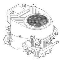
One-part system
: Mark on fuel hose grommet must
line up with mark on tank.
Multi-part system
: Center the connector in the fuel
tank’s opening and turn it so that
the tab (1) fits in the cutout (2).
: Push home the connector as far
as stop – it must snap into
1
2
position.
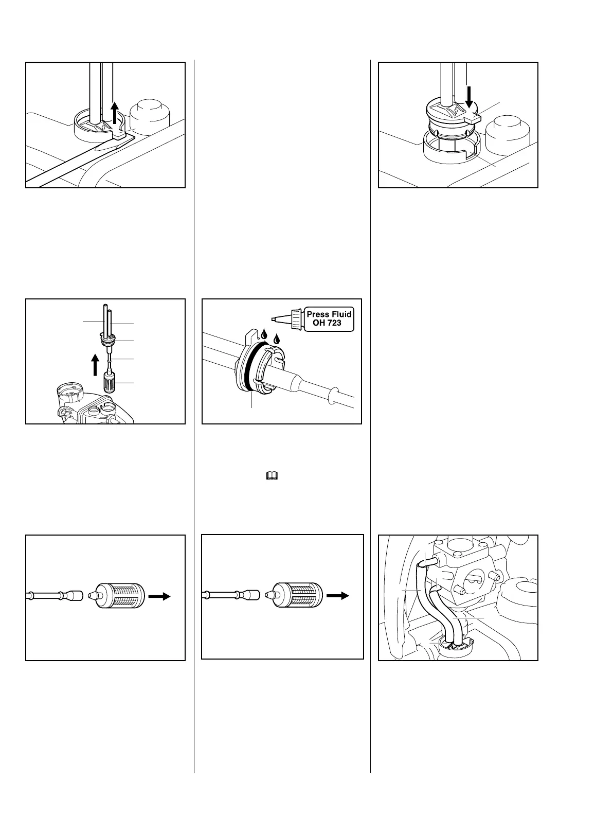
All systems
Check that hoses are properly
connected:
: Suction hose (1) from hose
connector with choke symbol to
fuel intake stub (2).
: Hose (3) from connector (4) to
return stub (5).
1
2
3
4
5
 Loading...