35Series 4180 Powerhead
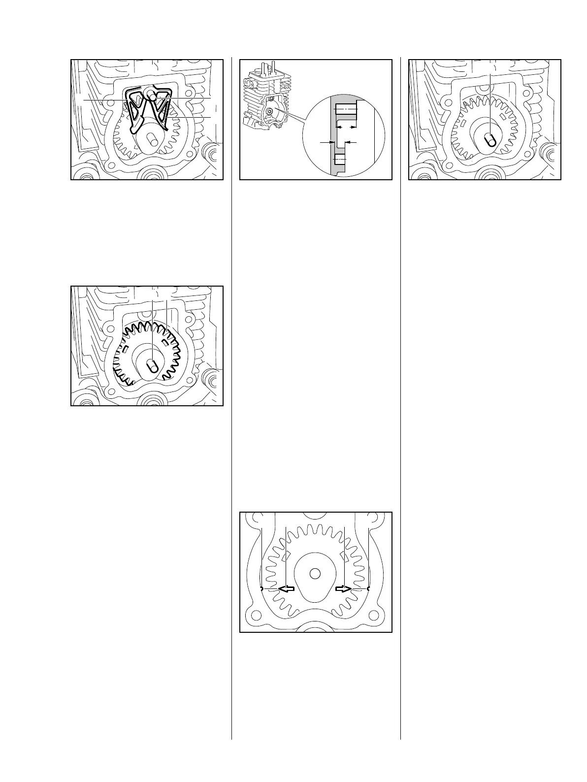
– Remove the pushrods, b 7.3
: Pull out the pin (1).
: Remove the cam followers (2).
: Pull out the pin (1).
: Remove the cam gear (2).
– Inspect the removed parts and
replace if necessary.
Reassemble in the reverse
sequence.
: Check the lengths of the pins (1).
Different lengths of pins have to be
installed to suit the type of cylinder.
Cylinders have bearing bores of
different depths:
: Permissible combinations are as
follows:
Bore Length of pin
a = 12.2 mm
b = 5.7 mm
28 mm
a = 10.7 mm
b = 4.2 mm
26.5 mm
– Set crankshaft to T.D.C.,
b 7.8.3
: Fit the cam gear so that the
marks (1 and 2) and (3 and 4) are
in alignment.
: Install the pin (1).
The marks must not move out of
position while the cam gear is being
fitted.
– Install the left-hand cam follower
first. It controls the inlet valve.
7.4 Cam Followers,
Cam Gear
 Loading...