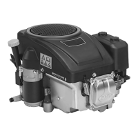
33Series 4180 Powerhead
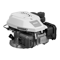
: Fit locking screw (1)
4180 890 2700 in spark plug
hole.
– Rotate crankshaft counter-
clockwise until the piston butts
against the locking screw.
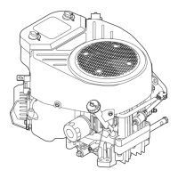
: Remove the hex. nut (1).
: Remove the starter cup (2).
– Remove the locking screw.
: Take out the screws (arrows).
: Carefully lift away the cam gear
cover (1).
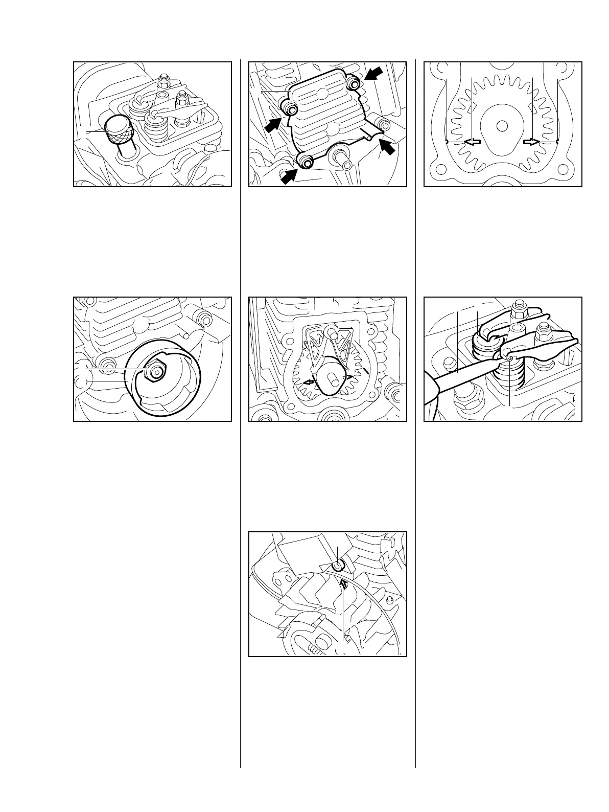
: Rotate crankshaft clockwise until
cam lobe points downward.
: Check that arrow (1) lines up with
the right-hand screw (2) on the
ignition module.
: Marks (arrows) on cam gear (2
and 3) must line up with the
notches (1 and 4) in the cylinder.
Cam gear cover must be fitted
before checking and adjusting valve
clearances.
: Insert feeler gauge
4180 893 6400 (2) between
rocker arm and valve stem.
The feeler gauge must slip through
with a certain resistance.
Inlet valve (1): 0.10 ± 0.02 mm
Exhaust valve (3): 0.10 ± 0.02 mm
 Loading...