- Slip the rubber boot off the
ignition lead.
- Cut new ignition lead to length
(see parts list or cut to same
length as old lead).
•
Use a pointed tool (awl or gimlet)
to pierce the center of the
ignition lead that is to be scre-
wed into the module.
- Slip the rubber boot over the
lead.
- Pack the high voltage output with
STIHL multipurpose grease - see
13.2.
Important:Do not use graphite
grease (Molykote) or silicone
insulating paste for this job.
- Screw home the ignition lead.
- Fit rubber boot on the high
voltage output.
- Fit cable retainer and spark plug
boot.
- Fit the ignition module - see
5.3.3.
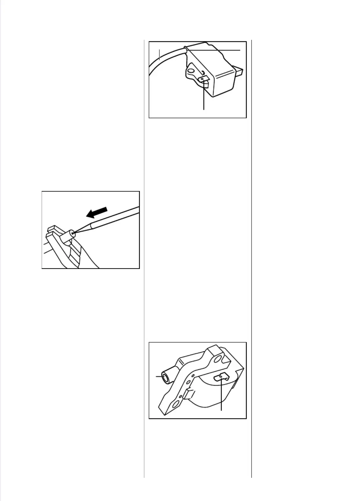
The ignition module accommo-
dates all the components required
to control ignition timing.
FS 120...350, FR 350
There are two electrical connec-
tions on the coil body:
1. the high voltage output (1) with
ignition lead (2)
2. the connector tag (3) for the
short circuit wire
A vibration damping pad is bonded
to the side of the ignition module.
FS 400/450, FR 450
There are two electrical connec-
tions on the coil body:
1. the high voltage output (1)
2. the connector tag (2) for the
short circuit wire
Accurate testing of the ignition
module is only possible with
sophisticated test equipment. For
this reason it is only necessary to
carry out a spark test in the work-
shop. A new ignition module must
be installed if no ignition spark is
obtained (after checking that
wiring and stop switch are in good
condition).
5.3 Ignition Module
2
5
0
R
A
0
9
5
1
2
V
A
3
3
8
R
A
1
4
2
V
A
2
5
0
R
A
0
5
4
2
1
3
V
A
FS 120, 200, 300, 350, 400, 450, FR 350, 450 25
 Loading...