•
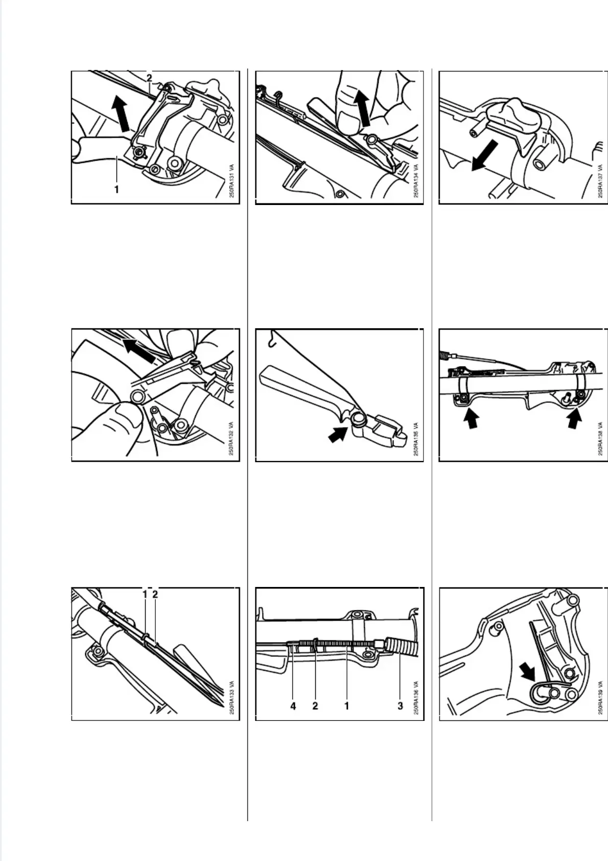
Pull throttle trigger (1) with
throttle cable (2) off the peg.
•
Disconnect throttle cable from
trigger.
•
Lift contact spring (1) a little and
remove the throttle cable (2).
•
Pull interlock lever with contact
spring off the peg.
•
Remove contact spring from
interlock lever.
Assemble in the reverse
sequence.
•
Check positions of throttle cable
(1), contact spring (2), protective
tube (3) and insulator (4).
- Tighten screws to 1.0 Nm
(0.75 lbf.ft).
- Remove the interlock lever -see
7.3.
•
Pull slide control off the handle
molding.
•
Remove screws from clamps.
- Take handle molding off the dri-
ve tube.
•
Remove torsion spring from peg.
7.4 Slide Control
(Loop Handle)
FS 120, 200, 300, 350, 400, 450, FR 350, 450 35
 Loading...