47MS 231, MS 231 C, MS 251, MS 251 C
Crimped side of terminal (1) must
face outwards.
: Connect the short circuit wire
terminal (1)
– the terminal must be pushed
fully home.
: Push the short circuit wire (2) and
protective tube (3) into the guide
so that "a" is about 5 mm.
– The protective tube must be
pushed into the grommet on the
air guide shroud as far as stop.
: Push short circuit wire (1) and
ground wire (2) fully into the
guides (arrows) and push the
retainer (3) into the slot in
retainer (4) until it snaps into
position.
– The wiring harness is secure.
2310RA123 TG
1
2
3
a
2310RA124 TG
1
2
3
4
: Fit the boot (1) on the spark plug
so that it is parallel to the air
guide shroud.
: Push the ignition lead (2) fully
into the guide (arrows).
– Note installed position of
ignition lead, see illustration.
Ignition lead and spark plug boot
must not touch the air guide shroud.
: Push the retainer (1) into the
slot (arrow) until it snaps into
position.
– Reassemble all other parts in the
reverse sequence.
7.4 Testing the Ignition
Module
To test the ignition module, use
either the ZAT 4 ignition system
tester 5910 850 4503 or the ZAT 3
ignition system tester
5910 850 4520.
2310RA125 TG
1
2
2310RA126 TG
1
The ignition test refers only to a
spark test, not to ignition timing.
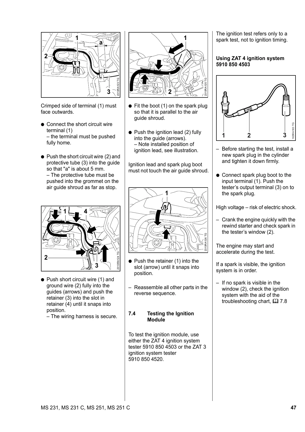
Using ZAT 4 ignition system
5910 850 4503
– Before starting the test, install a
new spark plug in the cylinder
and tighten it down firmly.
: Connect spark plug boot to the
input terminal (1). Push the
tester’s output terminal (3) on to
the spark plug.
High voltage – risk of electric shock.
– Crank the engine quickly with the
rewind starter and check spark in
the tester’s window (2).
The engine may start and
accelerate during the test.
If a spark is visible, the ignition
system is in order.
– If no spark is visible in the
window (2), check the ignition
system with the aid of the
troubleshooting chart, b 7.8
165RA183 TG
1
2
3
 Loading...