71MS 231, MS 231 C, MS 251, MS 251 C
10. Control Levers
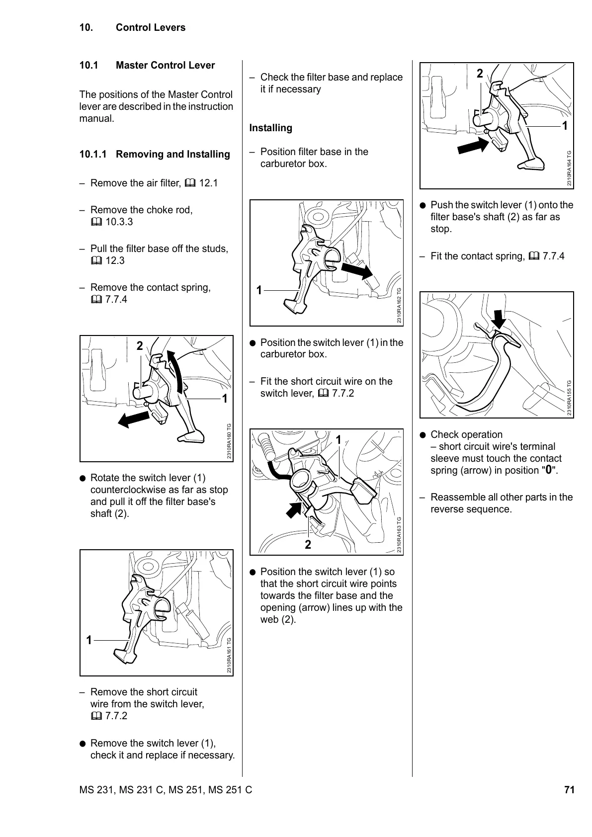
10.1 Master Control Lever
The positions of the Master Control
lever are described in the instruction
manual.
10.1.1 Removing and Installing
– Remove the air filter, b 12.1
– Remove the choke rod,
b 10.3.3
– Pull the filter base off the studs,
b 12.3
– Remove the contact spring,
b 7.7.4
: Rotate the switch lever (1)
counterclockwise as far as stop
and pull it off the filter base's
shaft (2).
– Remove the short circuit
wire from the switch lever,
b 7.7.2
: Remove the switch lever (1),
check it and replace if necessary.
2310RA160 TG
2
1
2310RA161 TG
1
– Check the filter base and replace
it if necessary
Installing
– Position filter base in the
carburetor box.
: Position the switch lever (1) in the
carburetor box.
– Fit the short circuit wire on the
switch lever, b 7.7.2
: Position the switch lever (1) so
that the short circuit wire points
towards the filter base and the
opening (arrow) lines up with the
web (2).
2310RA162 TG
1
2
2310RA163 TG
1
: Push the switch lever (1) onto the
filter base's shaft (2) as far as
stop.
– Fit the contact spring, b 7.7.4
: Check operation
– short circuit wire's terminal
sleeve must touch the contact
spring (arrow) in position "
0".
– Reassemble all other parts in the
reverse sequence.
2310RA164 TG
2
1
2310RA155 TG
 Loading...